


6
62--10458--00
90MA/MF004/006 UNITS
90MU004/006 UNITS
90MA/MU008/012 UNITS
90MU008/012 UNITS
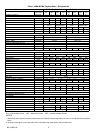
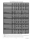
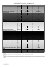
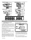
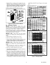
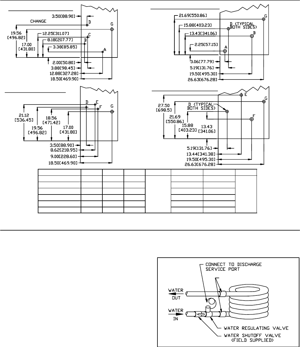
UNIT A* B* C* D* E F G
90MA/MF004 1/2 1/2 -- -- ¾ FPT -- -- -- -- 1.75
90MA/MF006 3/4 -- -- 3/4
-- -- -- -- (45)
90MA/MF008/012 1” 1” -- -- -- -- -- --
90MU004 -- -- -- -- -- -- 1/2 flare 1/2 flare
90MU006 -- -- -- -- -- -- 1/2 flare 1/2 flare
90MU008/012 -- -- -- -- -- -- 5/8 O.D. 3/4 O.D.
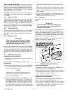
* A = Condenser In, B & C = Condenser Out, D = Condensate, all Female Pipe Thread, E = Liquid Refrigerant (field cut), F =
Refrigerant Discharge (field cut), G = Electrical Opening
Figure 5 Connection Locations
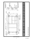
3.1 1 Check Compressor Spring Mounts
(008 & 012 size only)
The compressors are held rigid in shipment by bolts
extending through a washer, grommet and compressor
foot into a weld nut. Loosen each bolt (4 per
compressor) until compressor floats freely on springs.
Thenre--tighten bolts until thereis slightpressureon the
neoprene gasket. This will steady the compressor and
prevent start and stop rocking.
The compressors havereversible oil pumps that operate
in either direction; therefore, the direction of rotation
need not be checked.
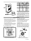
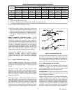
3.12 Make Condenser Connections
UNIT MOUNTED CONDENSER (90MA/MF) -- Condenser
water inlet and outlet connections are shown in
Figure 5. Piping arrangements for condenser cooling
water are shown in Figure 6.
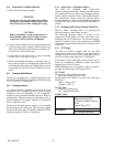
Connect condenser water supply and return lines as
indicated. W hen connecting water lines, hold the
condenser inlet and outlet stubs firmly with a wrench at
the female pipe thread hex fitting to prevent twisting.
Do not use water lines smaller than connection sizes
shown inFigure 5. Observeall applicableplumbingand
sanitary codes.
Install water--regulating valve in water supply line
outside cabinet as follows.
SeeFigure5
Figure 6 Typical Condenser Water Piping
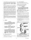
a. Route regulating valve capillary with its flare nut to
the port on refrigerant discharge line (Figure 1), us-
ing any convenient unused opening on side of unit.
Use a grommet in panel to prevent chafing of capil-
lary.
b. Remove cap from discharge line fitting.
c. Remove cotter pin taped to discharge line fitting. In-
sert pin, split end first, into regulating valve flare.