


9
62--10458--00
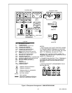
switch T--HIGH to energize liquid line solenoid (LLS)
[to activate the full evaporator coil and all compressor
cylinders]. If thermostat switch T--HIGH is not calling
for cooling, power fl ows to energize compressor
unloader solenoid (US) [to unload compressor
cylinders].
When room temperature falls to the cutout point of
T--LOW, switch T--LOW opens to de--energize CHR,
stopping the compressor motor and energizing CH. The
machine enters a stand--by s tate, ready to restart
automatically on room thermostat call for cooling.
Ifanysafetydeviceopens (CLO,SPS, DPS, IP, OLAor,
OLB) relay CHR is de -- energized, stopping the
compressor motor and ener gizing the crankcase heater.
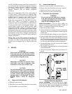
TO PLACE THE UNIT IN THE HEAT MODE: The
switch ( SW) is placed in the HEAT position. With
thermostat (T--LOW) calling for heating (closed to
contacts R & B), 24 volt control power flows through
manual reset temperature cutout MC to ener gize safety
relay H2. Poweralso flowsthrough airflow switch (AS)
and automatic cutout (AC) to energize operating relay
(H1). Energizing relays H1 and H2 closes contacts to
energize the heaters.
Placing SW in the FAN position de--energizes all
coolingor heatingcontrol circuitsin thesame manneras
activation of a safety switch. Placing SW in the OFF
position also de--energizes IFC t o stop the indoor fan
motor.
5. SERVICE
WARNING
Never reach into unit while fan is running.
Lock open and tag unit disconnect before
working on fan. Remove fuses and take them
with you after noting this on tag.
CAUTION
Sharp edges of coil fins are exposed. To pre-
vent injury, cover top of evaporator with
cardboard or a few layers of h eavy tape.
CAUTION
To avoid coil damage, cover evaporator face
with pl ywood or other rigid sheet material.
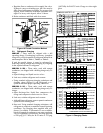
If any coil fins are mashed or bent, straight-
en with a coil fin comb of the proper tooth
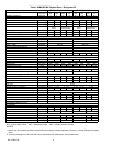
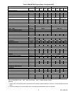
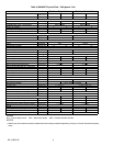
spacing (refer to “coil fins/inch” in Table 1
through Table 2). Check for refrigerant
leaks.
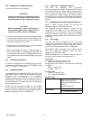
5.1 Return--Air Grille Removal
a. Pull grille out from top.
b. Pull grille up to release hinge pins from lower panel.
c. To reassemble, reverse procedure.
5.2 Access Panel Removal
a. Remove return--air grille as described above.
b. Remove the panel fastening screws now exposed.
c. Pull out and down to remove top panel.
d. Pull out and up to remove bottom panel.
5.3 Evaporator Fan Adjustment
WARNING
Never reach into unit while fan is running.
Lock open and tag unit disconnect before
working on fan. Remove fuses and take them
with you after noting this on tag.
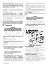
SPEED ADJUSTMENT -- The fan motor pulleys are
factory set at the fan speeds listed in Table 1, Table 3 or
Table 2. to change fan speed, do the following:
a. Shut off unit power supply.
b. Loosen fan belt by loosening fan motor from mount-
ing bracket. Do not loosenfanmotormounting brack-
et from unit.
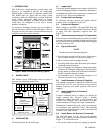
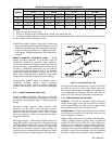
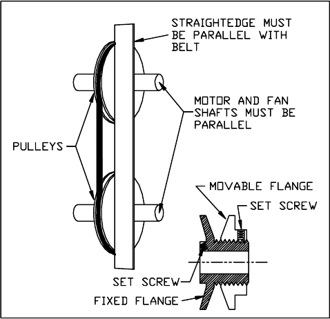
c. Loosen movable pulley flange set screw (Figure 8).
d. Screw movableflangetowardfixedflangeto increase
fan speed and a way from fixed flange to decrease
speed. Increasing fan speed increases load on motor.
Do not exceed maximum allowable fan speed or mo-
tor full load amps indicated on motor nameplate.
e. Set movable flange set screw at nearest flat of pulley
hub and tighten set screw.
f. Check pulley alignment and belt tension adjustment
as described below.
g. Check fan operation. Repeat above procedure as re-
quired.
Figure 8 Fan Pulley Adjustment
PULLEY ALIGNMENT -- Shut off unit power supply.
Loosen fan motor pulley set screws and slide fan pulley
along fan shaft. Make angular alignment by loosening
motor from mounting bracket (See Figure 8).