


3
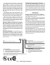
If variable frequency drives are utilized for system pumps,
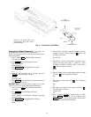
no pump control relays are specified. Each relay contains a red
light-emitting diode (LED), which indicates the relay coil is
energized. The pump control relays are located in the upper left
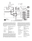
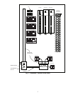
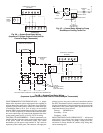
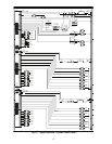
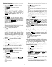
hand corner of the system control panel. See Fig. 4. Wiring is
shown in Fig. 5A-5C. Specifications for the pump control
relays are as follows:
Voltage Input: 24 vdc @ 15 mA, 14 vac @ 30 mA,
115 vac @ 20 mA, 230 vac
@ 20 mA.
Contact Rating: 10 A res. @ 115 vac,
7 A res. @ 230 vac/28 vdc,
N.O.:
1
/
6
hp @ 115 vac.
Temperature Range: –60 F to 185 F
Indication: LED
Enclosure: 18 ga. metal back
Dimensions: 5.125-in. x 3.125-in. x 2.5-in.
(HxWxD) or 5.125-in. x 9.5-in. x
2.5-in. (HxWxD)
OUTPUT TRANSDUCERS — For both stand-alone and
CCN systems (based on the stages of heat addition or rejection
required) the Aquazone™ system control panel can be ordered
with a combination of 2-stage and 4-stage output transducers to
provide 2, 4, 6, or 8 stages. The combination desired is speci-
fied in the 50RLP model nomenclature in digit 6 to specify heat
rejection stages and digit 7 to specify heat addition stages. See
Fig. 1. If variable speed cooling tower fan operation and/or
modulating valve operation for steam or water are utilized, no
output transducer card is specified. The output transducer is a
solid-state multi-stage device used for staging control from a
single analog signal. Output transducers are located in the
upper left hand corner of the Aquazone System Control Panel
underneath the pump control relays. See Fig. 4. Specifications
for the pump control relays are as follows:
Supply Voltage: 24 vac ± 10% @ 100 mA,
24 vdc ± 10% @ 50 mA
Input Signal: 4-20 mA
Output: 2 SPDT relays for 2-stage,
4 SPDT relays for 4-stage.
Relay rating: 5A @ 120 vac
Accuracy & repeatability: ± 1%
Set point adjustment: 25-turn potentiometers
Input impedance: 250 W (mA input), 10 kW
(V input)
Temperature Range: 32 F to 158 F
Humidity Limit: 5 to 95% relative humidity
non-condensing
Dimensions: 3.25-in. x 3.5-in. x 1.375-in.
(HxWxD) for 2-stage, 3.25-in. x
5.5-in. x 1.375-in. (HxWxD)
for 4-stage
Relay Differential: 0.5 mA or 0.375 V.
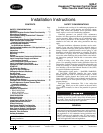
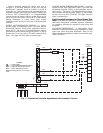
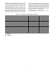
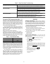
WSHP
WSHP
WSHP
WSHP
T-STAT
T-STAT
T-STAT
FLOW
SENSOR
TEMP.
SENSOR
AQUAZONE
SYSTEM
CONTROL
PANEL
T-STAT
AIR SEPARATOR
PUMP
BOILER
EXPANSION
TANK
COOLING
TOWER
LEGEND
Control Wiring
Loop Water Piping
Fig. 2 — Typical Stand-Alone WSHP System