


21
CONFIGURATION
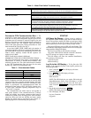
The Aquazone™ System Control Panel contains a Comfort
Controller 6400 programmed using the standard algorithms
and enhanced by BEST++™ custom programming. The
BEST++ Templates for some of the programs have been
removed to prevent field alterations. For other programs,
the templates are included to allow for jobsite customization.
For basic information about the algorithms please refer to the
Comfort Controller Overview and Configuration manual
(808-891). Default configurations are listed later in this section.
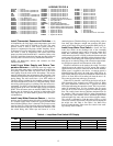
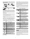
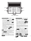
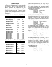
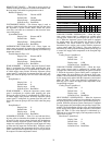
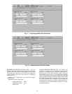
Hardware Points —
The hardware points are shown in
Table 11 and 12.
Table 11 — Hardware Points 1 to 32 (HWP01-32)
Table 12 — Hardware Points 33 to 64 (HWP33-64)
LOOP WATER FLOW SWITCH — This discrete input is
used to provide a signal that one of the loop water pumps is on.
If both pumps have been commanded to run and no water flow
is detected, then the system water source heat pumps will
run in the fan only mode for DDC (Direct Digital Control)
coordinated heat pump controllers, while the system relays for
thermostat systems will be turned off.
Loop Water Flow Switch:
Display Units Discrete ASCII
Default Value No
Display Range Yes/No
Network Access Read/Write
SYSTEM SUPPLY WATER TEMPERATURE — The sys-
tem supply water temperature is the temperature of the water
being pumped to the system of water source heat pumps. The
temperature is measured by a 10K Thermistor (MCI). This
output and sensor is required for proper function of the loop
and heat pumps.
System Supply Water Temperature:
Display Units degrees F (degrees C)
Default Value –40.0
Display Range –40.0-245.0
Network Access Read/Write
SYSTEM RETURN WATER TEMPERATURE — The sys-
tem return water temperature is the temperature of the water
returning from the system of water source heat pumps. This
temperature measured by a 10K Thermistor (MCI). This output
and sensor is provided for informational purpose and indicates
the average load caused by the normal operation of the heat
pumps.
System Return Water Temperature:
Display Units degrees F (degrees C)
Default Value –40.0
Display Range –40.0-245.0
Network Access Read/Write
SYSTEM WATER PRESSURE — This sensor is used to
measure the pressure of the supply water to the system of water
source heat pumps. This sensor should be located
2
/
3
of the way
down the supply water distribution piping or in a location that
will provide a good reference of the supply water pressure.
This sensor is used to control the speed of variable frequency
drives pumping water to the water source heat pumps. Each
water source heat pump may be equipped with a two position
isolation valve that may be closed when the compressors are
not energized in order to reduce the quantity of water being
pumped through the system.
System Water Pressure:
Display Units in. wg
Default Value 0.0
Display Range 0.0-5.0
Network Access Read/Write
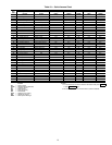
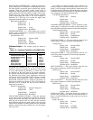
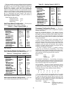
DESCRIPTION VALUE NAME
Loop Water Flow
Ye s F L O W
System Supply Water Temp
60.3 dF SSWT
System Return Water Temp
51.0 dF SRWT
System Diff. Pressure
0.00 PSIG SDP
Remote Occupancy Mode
Off RMTOCC
System
Enable ALLSYS
Override Input Zone 1
On OVRIZ1
Override Input Zone 2
On OVRIZ2
Pump Number 1 Speed
100.0% PUMP1
Pump Number 2 Speed
0.0% PUMP2
Cooling Tower 1 Level
0.0% CTL1
Cooling Tower 2 Level
0.0% CTL2
Boiler 1 Level
83.2% BLRL1
Boiler 2 Level
0.0% BLRL2
System for Zone 1
Enable SYSZ1
System for Zone 2
Enable SYSZ2
Override Input Zone 3
Off OVRIZ3
Override Input Zone 4
Off OVRIZ4
Override Input Zone 5
Off OVRIZ5
Override Input Zone 6
Off OVRIZ6
Override Input Zone 7
Off OVRIZ7
Override Input Zone 8
Off OVRIZ8
Override Input Zone 9
Off OVRIZ9
Override Input Zone 10
Off OVRIZ10
System for Zone 3
Disable SYSZ3
System for Zone 4
Disable SYSZ4
System for Zone 5
Disable SYSZ5
System for Zone 6
Disable SYSZ6
System for Zone 7
Disable SYSZ7
System for Zone 8
Disable SYSZ8
System for Zone 9
Disable SYSZ9
System for Zone 10
Disable SYSZ10
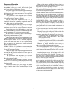
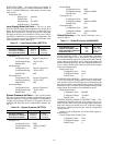
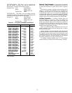
DESCRIPTION VALUE NAME
Override Input Zone 11
Off OVRIZ11
Override Input Zone 12
Off OVRIZ12
Override Input Zone 13
Off OVRIZ13
Override Input Zone 14
Off OVRIZ14
Override Input Zone 15
Off OVRIZ15
Override Input Zone 16
Off OVRIZ16
Override Input Zone 17
Off OVRIZ17
Override Input Zone 18
Off OVRIZ18
System for Zone 11
Disable SYSZ11
System for Zone 12
Disable SYSZ12
System for Zone 13
Disable SYSZ13
System for Zone 14
Disable SYSZ14
System for Zone 15
Disable SYSZ15
System for Zone 16
Disable SYSZ16
System for Zone 17
Disable SYSZ17
System for Zone 18
Disable SYSZ18