


10
INSTALLATION
Inspection —
Inspect the package contents for visual de-
fects that may have occurred during shipping. If there is any
damage, contact your local representative before proceeding.
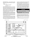
Mounting Location —
The Aquazone™ system control
panel should be located indoors. Be sure the location prevents
moisture and rain from coming into contact with the internal
hardware. Avoid areas where excessive moisture, corrosive
fumes, or vapors are present. The ambient temperature range at
the location should be between 32 to 125 F. Do not install the
Aquazone system control panel in electrical interference or
high radio frequency areas. Select a location which will be safe
from water damage and allow sufficient access for service and
wiring. For proper service of the Aquazone system control
panel, the following service clearances are recommended:
Height: 54 in.
Width: 42 in.
Depth: 36 in.
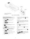
Mounting —
Mount the Aquazone system control panel to
a wall with screws or bolts (not provided). Attach through the
mounting holes provided in enclosure. Provide clearance to
open key-locked access door. Refer to the mounting sheet in-
cluded with the Aquazone system control panel for additional
detailed mounting instructions.
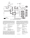
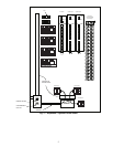
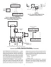
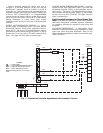
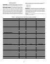
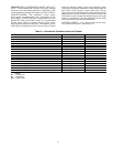
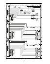
Wiring —
The Aquazone System Control Panel inputs and
outputs are shown in Table 2.
Table 2 — Aquazone System Control Panel Inputs and Outputs
PARAMETER POWER INPUT/OUTPUT TERMINAL
Processor Module
Loop Water Flow 24 vdc Input FLOW
System Supply Water Temp. 10 K thermistor Input SSWT
System Return Water Temp. 10 K thermistor Input SRWT
System Differential Pressure 4-20 mA Input SDP
Remote Occupied Mode 24 vdc Input RMTOCC
System Shut Down 24 vdc Input ALLSYS
Override Input for Zones 1 & 2 24 vdc Input OVRIZ1, OVRIZ2
Pump Number 1 & 2 Speeds 4-20 mA Output PUMP1, PUMP2
Cooling Tower 1 & 2 Speed/Level 4-20 mA Output CTL1, CTL2
Heat Source 1 & 2 Speed/Level 4-20 mA Output BLRL1, BLRL2
System Enable for Zone 1 & 2 24 vdc Output SYSZ1, SYSZ2
First Optional I/O Module
Override Input for Zone 3 to 10 24 vdc Input OVRIZ3 — OVRIZ10
System Enable for Zone 3 to 10 24 vdc Input SYSZ3 — SYSZ10
Second Optional I/O Module
Override Input for Zone 11 to 18 24 vdc Input OVRIZ11 — OVRIZ18
System Enable for Zone 11 to 18 24 vdc Input SYSZ11 — SYSZ18
Pump Control
Occupancy Schedule 1 to 18 Logic Internal Parameter —
Network Global Schedule 65 to 82 Logic Internal Parameter —
Override Input 1 to 18 Logic Input OVRIZ1 — OVRIZ18
System Enable Outputs Logic Output SYSZ1 — SYSZ18
Remote Occupied Mode Logic Input RMTOCC
System Differential Pressure Logic Input SDP
System Differential Pressure Set point Logic User Configuration —
Loop Water Flow Logic Input FLOW
Control Type Logic User Configuration —
Pump Number 1 & 2 Speeds Logic Output PUMP1, PUMP2
Shut Down Command Logic Output ALLSYS
Heat Rejection Control
System Supply Water Temp. Logic Input SSWT
System Return Water Temp. Logic Input SRWT
System Loop Temperature Set points Logic User Configuration —
Fluid Cooler/Tower Control Logic User Configuration —
Loop Water Flow Logic Input FLOW
Cooling Tower 1 & 2 Speed/Level Logic Output CTL1, CTL2
Heat Addition Control
System Supply Water Temp. Logic Input SSWT
System Return Water Temp. Logic Input SRWT
System Loop Temperature Set points Logic User Configuration —
Boiler Control Type Logic User Configuration —
Loop Water Flow Logic Input FLOW
Boiler 1 & 2 Speed/Level Logic Output BLRL1, BLRL2