


13
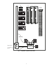
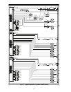
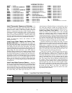
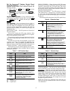
LEGEND FOR FIG. 8
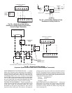
Install Thermostat, Sensors and Switches —
In
all installations, the loop supply water temperature sensor and
water flow switch must be installed in the field. The water
pressure sensor is used to sense water system pressure to
operate in conjunction with pump variable frequency drives.
A thermostat is used in stand-alone systems. A space tempera-
ture sensor is used in conjunction with water source heat
pumps provided with PremierLink™ controllers. Refer to the
accessory installation instructions literature provided with each
accessory that is used for accessory installation instructions.
NOTE: All thermostats, sensors, and switches are field-
installed accessories.
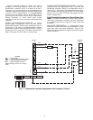
Install Loop Water Supply and Return Tem-
perature Sensors —
Install the water loop supply sen-
sor in the main water supply, located before the water source
heat pumps. Install the water loop return sensor in the return
water piping from the water source heat pumps. The sensors
must be inserted fully into an immersion well (provided). Seal
immersion well threads with tape and install into pipe tee or re-
ducing fitting. The well screws into a
1
/
2
-in. NPT saddle (or
Thredolet fitting) furnished by the installing contractor. Screw
the sensor into the well via the
1
/
8
-in. NPT brass fitting. Termi-
nate wiring with butt splice or soldering. Wire nuts are not rec-
ommended. Use full 8 ft of lead length provided to avoid mois-
ture migration up the wire. Wire the supply sensor to terminals
SSWT. Wire the return sensor to terminals SRWT. See Fig. 8.
Sensors may be located in any position in relationship to the
main supply line. Use shield cable to protect from any electri-
cal interference.
Install Loop Water Pressure Sensor —
Install the
pressure sensor on the discharge side of the circulating pump(s)
in a common supply main so that total system pressure rather
than individual pump(s) flow is detected. The pressure sensor
must be placed in a vertical position and must match the actual
water flow direction with flow switch direction indicators. Seal
the switch fitting with Teflon tape and insert in a
1
/
4
-in.
standard pipe tee (Thredolet fitting) or reducing fitting, with at
least three pipe diameters straight run upstream and down-
stream of the switch. Wire sensor to terminals SDP. See Fig. 8.
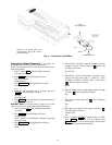
Install Loop Water Flow Switch —
Install the loop
water flow switch on the discharge side of the circulating
pump(s) in a common supply main so that total system flow
rather than individual pump(s) flow is detected. The flow
switch must be placed in a vertical position and must match the
actual water flow direction with flow switches direction indica-
tors. Seal the switch fitting with Teflon tape and insert in a stan-
dard pipe tee or reducing fitting, with at least three pipe diame-
ters straight run upstream and downstream of the switch.
Electrical connection can be made to the switch. Two wires
should be run to the switch for 24 VAC power. The switch is
supplied with wire leads for connection to the FLOW terminal.
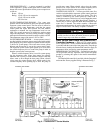
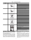
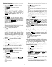
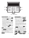
When power is supplied to the device, a warm-up period is
initiated. During this period, the right green LED will be lit.
Each LED to the left is successively lit until the farthest left red
LED is lit. Each LED will be turned off when the next is lit.
The warm-up period may take up to 30 seconds.
When flow is detected, a red LED at the far left will be lit.
With increasing flow, successive red LEDs will be lit. When
the switch determines sufficient flow is present, the amber
LED lights indicating the output has closed. This is not an indi-
cation of minimum flow. As flow increases, the first green
LED will be lit. Each successive green LED indicates greater
flow. The switch closure does not indicate minimum flow for
the machine. With one green LED lit, minor fluctuations in
water flow may cause nuisance alarms. Additional green LEDs
indicate higher flow rates, and can avoid the nuisance alarms.
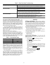
The switch is calibrated to light the amber LED at a fluid
velocity of 0.8 ft/sec (0.24 m/sec). The flow rate will depend on
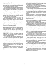
the nozzle size. See Table 4. See Table 5 for Water Flow
Switch Troubleshooting. If the water flow switch is not work-
ing correctly, refer to Table 5.
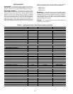
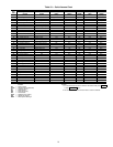
Table 4 — Loop Water Flow Switch LED Display
ALLSYS —
System
BLRL1 —
Heat Source 1 Speed/Level
BLRL2 —
Heat Source 2 Speed/Level
CB —
Circuit Breaker
CTL1 —
Cooling Tower 1 Speed/Level
CTL2 —
Cooling Tower 2 Speed/Level
FLOW —
Loop Water Flow
OVRIZ1 —
Override Input for Zone 1
OVRIZ2 —
Override Input for Zone 2
OVRIZ3 —
Override Input for Zone 3
OVRIZ4 —
Override Input for Zone 4
OVRIZ5 —
Override Input for Zone 5
OVRIZ6 —
Override Input for Zone 6
OVRIZ7 —
Override Input for Zone 7
OVRIZ8 —
Override Input for Zone 8
OVRIZ9 —
Override Input for Zone 9
OVRIZ10 —
Override Input for Zone 10
OVRIZ11 —
Override Input for Zone 11
OVRIZ12 —
Override Input for Zone 12
OVRIZ13 —
Override Input for Zone 13
OVRIZ14 —
Override Input for Zone 14
OVRIZ15 —
Override Input for Zone 15
OVRIZ16 —
Override Input for Zone 16
OVRIZ17 —
Override Input for Zone 17
OVRIZ18 —
Override Input for Zone 18
PCB —
Comfort Controller Circuit Board
PUMP1 —
Pump Number 1
PUMP2 —
Pump Number 2
RMTOCC —
Remote Occupied Mode
SDP —
System Differential Pressure
SRWT —
System Return Water Temperature
SSWT —
System Supply Water Temperature
SYSZ1 —
System for Zone 1
SYSZ2 —
System for Zone 2
SYSZ3 —
System for Zone 3
SYSZ4 —
System for Zone 4
SYSZ5 —
System for Zone 5
SYSZ6 —
System for Zone 6
SYSZ7 —
System for Zone 7
SYSZ8 —
System for Zone 8
SYSZ9 —
System for Zone 9
SYSZ10 —
System for Zone 10
SYSZ11 —
System for Zone 11
SYSZ12 —
System for Zone 12
SYSZ13 —
System for Zone 13
SYSZ14 —
System for Zone 14
SYSZ15 —
System for Zone 15
SYSZ16 —
System for Zone 16
SYSZ17 —
System for Zone 17
SYSZ18 —
System for Zone 18
T —
Transformer
TB —
Terminal Block
TBP —
Terminal Block or Pin Connector
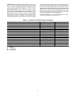
SIZE
SCHEDULE 40 PIPE
O.D. (in.) Wall Thickness (in.) I.D. (in.) Area (Ft
2
)GPM
4
4.5 .237 4.026 0.09 32
5
5.563 .258 5.047 0.14 50
6
6.625 .28 6.065 0.20 72
8
8.625 .322 7.981 0.35 125