5
NOTE: Consult the Controls and Troubleshooting Guide for in
depth instructions on using and configuring the ComfortLink
control. The following instructions are written for the Scrolling
Marquee Display or Navigator™ accessory.
1. The ComfortLink control must be configured to use the
electric heater accessory. A password may be required to
edit the configurations depending on the previous settings
configured in the unit. Default password is “1111.”
2. To configure the ComfortLink control, use the arrow keys
to scroll the red LED on the display to the “Configuration”
position and press ENTER.
3. Use the arrow keys to scroll down until the display shows
“HEAT.” This is the Heating Configuration Sub Mode.
Press ENTER.
4. The ComfortLink control will display the Type of Heat
(HT.TY) setting. Press ENTER once to select the HT.TY
setting for configuration. Press ENTER again. A “0” will
begin flashing.
5. Use the arrow keys to change the configuration from “0”
(No Heat) to “2” (Electric Heat) and press ENTER. Press
ESCAPE to save the setting.
6. For single-stage electric heaters only (10 kW or less), the
Number of Heat Stages must be changed from 2 to 1.
a. Use the arrow keys to scroll down to the Number of Heat
Stages setting (N.HTR). Press ENTER to select the
N.HTR setting for configuration.
b. Press ENTER again. Configuration value will flash.
c. Use the arrow keys to change the configuration from “2”
(2 stages of heat) to “1” (one stage of heat) and press
ENTER.
d. Press ESCAPE to save the configuration change.
7. Configuration of ComfortLink™ control is now complete.
Pressing ESCAPE multiple times will return the
display to the auto-scroll setting.
8. Close and secure all access doors.
THERMOSTAT CONTROL
For heat mode to operate, the accessory thermostat must be
connected to the corresponding W1 and W2 terminals on the field
connection terminal board located in the unit control box.
SPACE TEMPERATURE CONTROL
(Direct Wired or CCN)
For heat mode to operate, a jumper must be connected between R
and W1 on the field-connection terminal board located in the unit
control box.
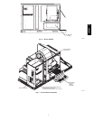
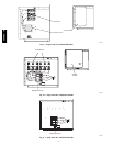
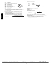
TERMINAL
BLOCKS
(3-PHASE SHOWN)
C06187
Fig. 6 − Single Point Box
CRSINGLE028A00, CRSINGLE030A00
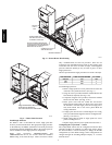
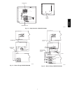
FUSE BLOCK
(3-PHASE SHOWN)
HINGED COVER
C06188
Fig. 7 − Single Point Box
CRSINGLE029A00, CRSINGLE031A00
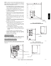
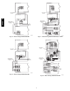
FUSE BLOCK
TERMINAL BLOCK
HINGED COVER
C06189
Fig. 8 − Single Point Box CRSINGLE032A00
50PG03−16