


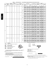
2
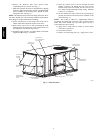
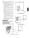
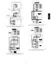
6. Remove the block-off plate from electric heater
compartment and save screws. (See Fig. 2.)
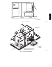
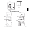
7. Slide heater module into heater compartment by aligning
the heater frame with the heater opening. Do NOT handle
heater assembly by the heating coils. Handle by sheet
metal panel only. (See Fig. 3.)
NOTE: The 50PG16 heater bottom-rear flange will secure into a
slot on the internal cross rail when fully installed. Check that the
heater flange is straight and flat before installing.
8. Secure electric heater to unit using screws from item 6.
Heater will attach to the block off plate screw holes.
9. Route heater power wires to the left through the foam
bushing and to the single point power connection box in
the compressor section. (See Fig. 3 and 4.)
10. Install the single point box, if required. Refer to the Install
Single Point Box, Step 2, for details.
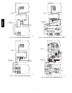
11. Route the control wires to the left through the foam
bushing. Connect to the mating plug (PL−3) in the wire
harness in the indoor fan section. Do not route 24 volt
low voltage wiring beside high voltage wiring. Maintain
at least a 1−2” separation.
12. Set the manual reset limit switch on the fan housing by
pressing the button located between the terminals on the
switch. (See Fig. 3.)
NOTE: This switch is added as a supplemental means to
de−energize the electric heat contactor in case of indoor airflow
failure. The switch should only open and require reset for a
switch temperature above 200_F.
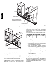
13. Apply heater wiring label to inside of electric heater
section door. (See Fig. 5.)
14. Close all access doors.
15. Remove “Lock−Out Tag−Out” tag. Apply power to unit.
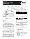
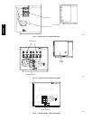
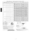
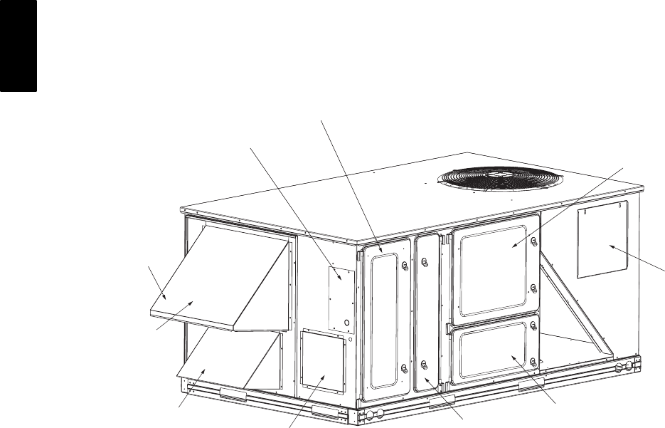
CONTROL BOX
AND COMPRESSOR
ACCESS DOOR
OUTDOORAIR
SCREEN
(HIDDEN)
FILTERACCESS DOOR
INDOOR MOTOR
ACCESS DOOR
ECONOMIZER
HOOD
BAROMETRIC
RELIEF DAMPER
HOOD
ELECTRICAL
OPTIONS PANEL
BASEPAN CONNECTIONS
ACCESS PANEL
CONDENSER COI
L
ACCESS PANEL
ELECTRIC HEAT
ACCESS DOOR
C06182
Fig. 1 − Panel Locations
50PG03−16