


27
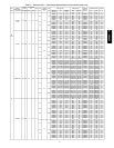
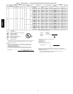
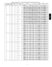
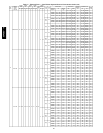
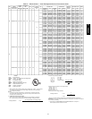
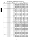
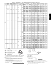
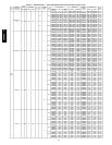
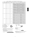
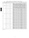
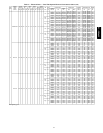
Table 2 — Electrical Data — Units With Optional Powered Convenience Outlet (cont)
UNIT
50PG
NOMINAL
POWER
SUPPLY
VOLTS-PH-HZ
VOLTAGE
RANGE
COMPRESSOR
OFM
FLA
IFM
FLA
POWER
EXHAUST
FLA
IFM
TYPE
ELECTRIC HEAT POWER SUPPLY
CRSINGLE
PART NO.
(NOTE3)
DISCONNECT SIZE
WIRING
FIG.
NO.
MIN MAX RLA LRA
CRHEATER
PART
NO.
FLA
NOMINAL
KW*
MCA MOCP† FLA LRA
08
(cont)
575-3-60 518 632 6.4 30.0 0.8 2.0 Ċ
Low
Ċ Ċ Ċ 20.1 20 Ċ 21 86 Ċ
239A00 13.9 15.0 22.0 25 030A00 21 86 15
240A00 23.1 25.0 33.5 35 030A00 31 86 15
241A00 32.3 35.0 45.1 50 030A00 41 86 15
242A00 37.0 40.0 50.9 60 030A00 47 86 15
High
Ċ Ċ Ċ 20.6 20 Ċ 22 104 Ċ
239A00 13.9 15.0 23.0 25 030A00 22 104 15
240A00 23.1 25.0 34.5 35 030A00 32 104 15
241A00 32.3 35.0 46.1 50 030A00 42 104 15
242A00 37.0 40.0 51.9 60 030A00 48 104 15
575-3-60 518 632 6.4 30.0 0.8 2.8 3.0
Low
Ċ Ċ Ċ 19.9 25 Ċ 21 88 Ċ
239A00 13.9 15.0 25.7 30 030A00 24 88 15
240A00 23.1 25.0 37.3 40 030A00 34 88 15
241A00 32.3 35.0 48.8 50 030A00 45 88 15
242A00 37.0 40.0 54.6 60 030A00 50 88 15
High
Ċ Ċ Ċ 20.7 25 Ċ 22 100 Ċ
239A00 13.9 15.0 26.7 30 030A00 25 100 15
240A00 23.1 25.0 38.3 40 030A00 35 100 15
241A00 32.3 35.0 49.8 50 030A00 46 100 15
242A00 37.0 40.0 55.6 60 030A00 51 100 15
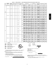
09
208/230-3-60 187 253 16.0 91 1.5
5.2
Ċ
Low
Ċ Ċ Ċ/Ċ 49.1/49.1 60/60 Ċ 52/52 223/223 Ċ
225A00 20.0/23.1 7.5/10.0 49.1/49.1 60/60 030A00 52/52 223/223 15
226A00 30.0/34.6 11.3/15.0 50.0/55.2 60/60 030A00 52/52 223/223 15
227A00 50.0/57.7 18.8/25.0 75.1/84.1 80/90 031A00 69/78 223/223 16
228A00 70.0/80.8 26.3/35.0 100.1/113.0 110/125 031A00 92/104 223/223 17
229A00 80.0/92.4 30.0/40.0 112.6/127.4 125/150 031A00 104/118 223/223 17
10.2 High
Ċ Ċ Ċ/Ċ 54.1/54.1 60/60 Ċ 58/58 266/266 Ċ
225A00 20.0/23.1 7.5/10.0 54.1/54.1 60/60 031A00 58/58 266/266 15
226A00 30.0/34.6 11.3/15.0 56.3/61.5 60/70 031A00 58/58 266/266 15
227A00 50.0/57.7 18.8/25.0 81.3/90.4 90/100 031A00 75/84 266/266 16
228A00 70.0/80.8 26.3/35.0 106.3/119.2 110/125 031A00 98/110 266/266 17
229A00 80.0/92.4 30.0/40.0 118.8/133.7 125/150 031A00 109/123 266/266 17
5.2
3.0
Low
Ċ Ċ Ċ/Ċ 52.1/52.1 60/60 Ċ 55/55 227/227 Ċ
225A00 20.0/23.1 7.5/10.0 52.1/52.1 60/60 031A00 55/55 227/227 15
226A00 30.0/34.6 11.3/15.0 53.8/59.0 60/60 031A00 55/55 227/227 15
227A00 50.0/57.7 18.8/25.0 78.8/87.9 80/90 031A00 72/81 227/227 16
228A00 70.0/80.8 26.3/35.0 103.8/116.7 110/125 031A00 96/108 227/227 17
229A00 80.0/92.4 30.0/40.0 116.3/131.2 125/150 031A00 107/121 227/227 17
10.2 High
Ċ Ċ Ċ/Ċ 57.1/57.1 70/70 Ċ 61/61 270/270 Ċ
225A00 20.0/23.1 7.5/10.0 57.1/57.1 70/70 030A00 61/61 270/270 15
226A00 30.0/34.6 11.3/15.0 60.0/65.2 70/70 030A00 61/61 270/270 15
227A00 50.0/57.7 18.8/25.0 85.1/94.1 90/100 031A00 78/87 270/270 16
228A00 70.0/80.8 26.3/35.0 110.1/123.0 125/125 031A00 101/114 270/270 17
229A00 80.0/92.4 30.0/40.0 122.6/137.4 125/150 031A00 113/127 270/270 17
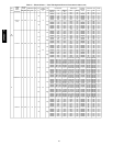
460-3-60 414 506 7.1 46 0.8
2.6
Ċ
Low
Ċ Ċ Ċ 22.2 25 Ċ 24 112 Ċ
232A00 11.5 10.0 22.2 25 030A00 24 112 15
233A00 17.3 15.0 27.6 30 030A00 25 112 15
234A00 28.9 25.0 42.1 45 030A00 39 112 15
235A00 40.4 35.0 56.5 60 030A00 52 112 15
236A00 46.2 40.0 63.7 70 033A00 59 112 19
4.8 High
Ċ Ċ Ċ 24.4 30 Ċ 26 134 Ċ
232A00 11.5 10.0 24.4 30 030A00 26 134 15
233A00 17.3 15.0 30.4 35 030A00 28 134 15
234A00 28.9 25.0 44.8 45 030A00 41 134 15
235A00 40.4 35.0 59.2 60 030A00 54 134 15
236A00 46.2 40.0 66.5 70 033A00 61 134 19
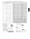
LEGEND
FLA − Full Load Amps
HACR − Heating, Air Conditioning and Refrigeration
IFM − Indoor − Fan Motor
LRA − Locked Rotor Amps
MCA − Minimum Circuit Amps
MOCP − Maximum Overcurrent Protection
NEC − National Electrical Code
OFM − Outdoor−Fan Motor
RLA − Rated Load Amps
* Heater capacity (kW) is based on heater voltage of 208 v, 240 v, or 480 v. If power distribu-
tion voltage to unit varies from rated heater voltage, heater kW will vary accordingly.
† Fuse or HACR circuit breaker.
NOTES:
1. In compliance with NEC requirements for multimotor and combination load equip-
ment (refer to NEC Articles 430 and 440), the overcurrent protective device for the
unit shall be fuse or HACR breaker.
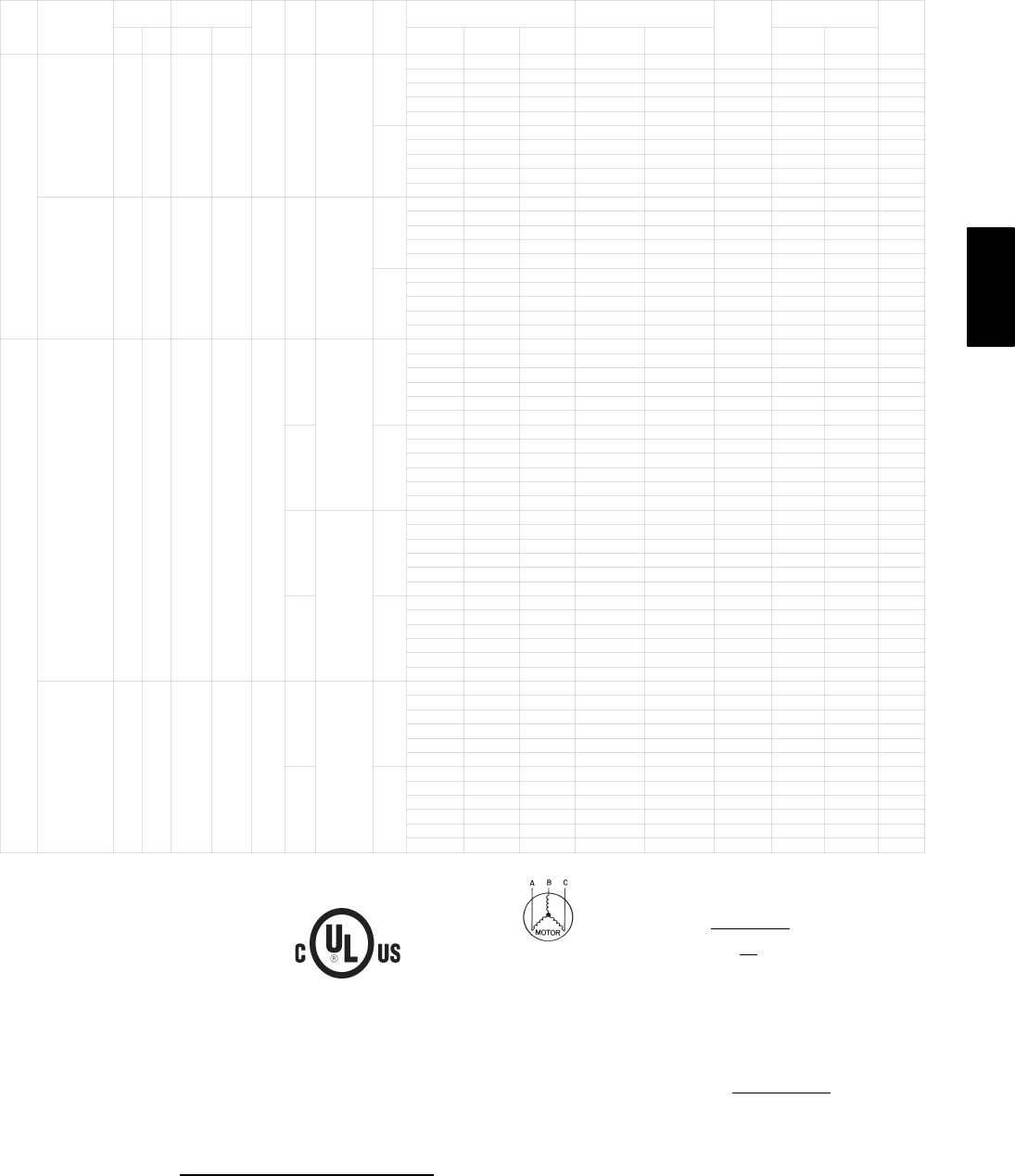
2. Unbalanced 3-Phase Supply Voltage
Never operate a motor where a phase imbalance in supply voltage is greater than
2%. Use the following formula to determine the percentage of voltage imbalance.
% Voltage Imbalance = 100 x
max voltage deviation from average voltage
average voltage
Example: Supply voltage is 460-3-60
AB = 224 v
BC = 231 v
AC = 226 v
Average Voltage =
224 + 231 + 226
3
681
3
=
227
=
Determine maximum deviation from average voltage.
(AB) 227 – 223 = 3 v
(BC) 231 – 227 = 4 v
(AC) 227 – 226 = 1 v
Maximum deviation is 4 v.
Determine percent of voltage imbalance.
% Voltage Imbalance = 100 x
4
227
= 1.76%
This amount of phase imbalance is satisfactory as it is below the maximum allowable 2%.
IMPORTANT: If the supply voltage phase imbalance is more than 2%, contact your local electric
utility company immediately.
3. Single point kits CRSINGLE028A00 and CRSINGLE030A00 are not required if
field−supplied pressure connectors are used.
50PG03−16