18
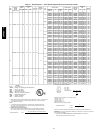
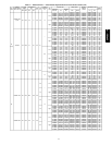
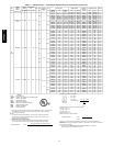
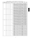
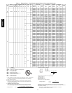
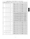
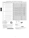
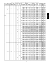
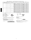
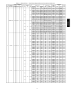
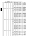
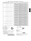
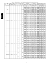
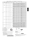
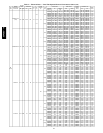
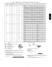
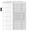
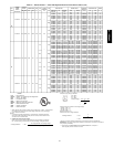
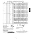
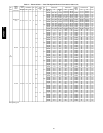
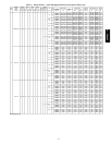
Table 1 — Electrical Data — Units Without Optional Powered Convenience Outlet (cont)
UNIT
50PG
NOMINAL
POWER
SUPPLY
VOLTS-PH-HZ
VOLTAGE
RANGE
COMPRESSOR
(EA.)
OFM
FLA
IFM
FLA
POWER
EXHAUST
FLA
IFM
TYPE
ELECTRIC HEAT POWER SUPPLY
CRSINGLE
PART
NO.(NOTE3)
DISCONNECT
SIZE
WIRING
FIG.
NO.
MIN MAX RLA LRA
CRHEATER
PART
NO.
FLA
NOMINAL
KW*
MCA MOCP† FLA LRA
12
(cont)
575-3-60 518 632 6.1 40.0 0.8
2.8
Ċ
Low
Ċ Ċ Ċ 20.1 20 Ċ 21 124 Ċ
239A00 13.9 15.0 20.8 25 030A00 21 124 15
240A00 23.1 25.0 32.4 35 030A00 32 124 15
241A00 32.3 35.0 43.9 45 030A00 42 124 15
242A00 37.0 40.0 49.7 50 030A00 48 124 15
243A00 46.2 50.0 49.7 60 030A00 58 124 15
3.3 High
Ċ Ċ Ċ 18.6 20 Ċ 20 142 Ċ
239A00 13.9 15.0 21.4 25 030A00 20 142 15
240A00 23.1 25.0 33.0 35 030A00 30 142 15
241A00 32.3 35.0 45.1 45 030A00 41 142 15
242A00 37.0 40.0 50.3 50 030A00 46 142 15
243A00 46.2 50.0 50.3 60 030A00 57 142 15
2.8
3.0
Low
Ċ Ċ Ċ 21.1 25 Ċ 23 110 Ċ
239A00 13.9 15.0 24.6 25 030A00 23 110 15
240A00 23.1 25.0 36.1 40 030A00 33 110 15
241A00 32.3 35.0 47.7 50 030A00 44 110 15
242A00 37.0 40.0 53.4 60 030A00 49 110 15
243A00 46.2 50.0 53.4 60 030A00 60 110 15
3.3 High
Ċ Ċ Ċ 21.1 25 Ċ 23 110 Ċ
239A00 13.9 15.0 24.6 25 030A00 23 110 15
240A00 23.1 25.0 36.1 40 030A00 33 110 15
241A00 32.3 35.0 47.7 50 030A00 44 110 15
242A00 37.0 40.0 53.4 60 030A00 49 110 15
243A00 46.2 50.0 53.4 60 030A00 60 110 15
LEGEND
FLA − Full Load Amps
HACR − Heating, Air Conditioning and Refrigeration
IFM − Indoor − Fan Motor
LRA − Locked Rotor Amps
MCA − Minimum Circuit Amps
MOCP − Maximum Overcurrent Protection
NEC − National Electrical Code
OFM − Outdoor−Fan Motor
RLA − Rated Load Amps
* Heater capacity (kW) is based on heater voltage of 208 v, 240 v, or 480 v. If power distribu-
tion voltage to unit varies from rated heater voltage, heater kW will vary accordingly.
† Fuse or HACR circuit breaker.
NOTES:
1. In compliance with NEC requirements for multimotor and combination load equip-
ment (refer to NEC Articles 430 and 440), the overcurrent protective device for the
unit shall be fuse or HACR breaker.
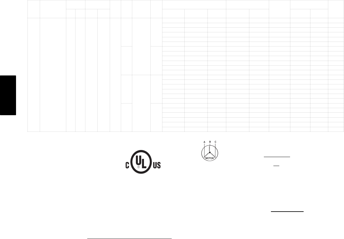
2. Unbalanced 3-Phase Supply Voltage
Never operate a motor where a phase imbalance in supply voltage is greater than
2%. Use the following formula to determine the percentage of voltage imbalance.
% Voltage Imbalance = 100 x
max voltage deviation from average voltage
average voltage
Example: Supply voltage is 460-3-60
AB = 224 v
BC = 231 v
AC = 226 v
Average Voltage =
224 + 231 + 226
3
681
3
=
227
=
Determine maximum deviation from average voltage.
(AB) 227 – 223 = 3 v
(BC) 231 – 227 = 4 v
(AC) 227 – 226 = 1 v
Maximum deviation is 4 v.
Determine percent of voltage imbalance.
% Voltage Imbalance = 100 x
4
227
= 1.76%
This amount of phase imbalance is satisfactory as it is below the maximum allowable 2%.
IMPORTANT: If the supply voltage phase imbalance is more than 2%, contact your local electric
utility company immediately.
3. Single point kits CRSINGLE028A00 and CRSINGLE030A00 are not required if
field−supplied pressure connectors are used.
50PG03−16