


4
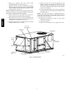
HEATERASSEMBLY
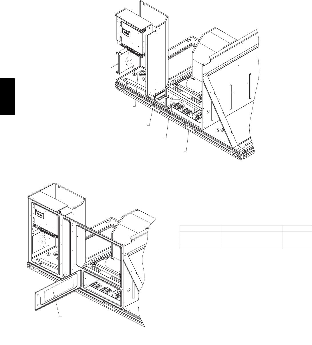
CONNECT PL3 PLUG
AND RECEPTACLE
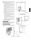
ROUTE HEATER POWER WIRES
THROUGH RACEWAYAND BEHIND
COMPRESSORS (COMPRESSORS
REMOVED FOR CLARITY)
POWER WIRES ARE
ROUTED INTO BOTTOM
OF SINGLE POINT BOX
SINGLE
POINT
BOX
C06185
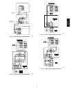
Fig. 4 − Electric Heater Wire Routing
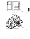
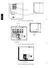
AFFIX HEATER WIRING LABEL DIAGRAM
SUPPLIED WITH HEATERS ON
FOIL FACE INSULATION IN AREA SHOWN
C06186
Fig. 5 − Heater Label Location
Install Single Point Box
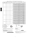
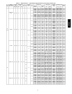
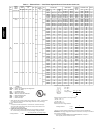
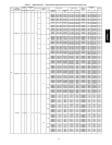
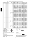
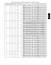
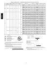
See Tables 1 and 2 to determine the correct single point box
accessory for the selected heater. The appropriate single point box
is determined by the MOCP (maximum overcurrent protection)
for the heater and unit combination. Refer to the correct figure for
correct installation of the single point box components.
Single point accessories CRSINGLE028A00 and
CRSINGLE030A00 are for use on units where the combined
MOCP rating is less than 60 amps. These accessories contain
only a terminal block; no fuses are provided. Fuses are not
required per the National Electrical Code in these single point
accessories since the circuit is below 60 amps. Field−supplied
pressure connectors (Kerneys) may be used in place of these
single point boxes.
All fuses provided in the single point boxes are rated at 60 amps.
UNIT VOLTAGE FUSE VOLTAGE RATING UL CLASS
208/230
250 RK5
460
600 T
575
600 T
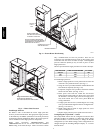
To install single point box:
1. Remove single point box access panel located on the end
of the unit. Save panel and screws. (See Fig. 3.)
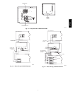
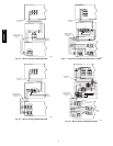
2. Using the screws provided, install the terminal blocks and
fuse blocks (if required). (See Fig. 6-12.)
3. If required, using the wires provided, connect the terminal
block to the fuse block. (See Fig. 13-22.)
4. Route power wires from the control box and electric
heaters into the single point box. Route power wires from
the disconnect into the single point box through power
entry hole located next to the access panel. Make all
wiring connections.
5. If single point box has fuses, install hinged cover using
rivets provided. Install magnetic latch in rectangular hole.
(See Fig. 7-10 and 12.)
6. Install wiring label on back of single point box access
panel or on hinged cover.
7. Replace single point box access panel removed in item 1.
Configuring the ComfortLinkt Control
The ComfortLink control must be configured for Electric Heat
(default is No Heat). In addition, if a single-stage electric heater
has been installed, it will be necessary to change the N.HTR
configuration (2 is the default setting). These configurations are
changed through the Scrolling Marquee Display or a Carrier
network device.
50PG03−16