


9
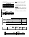
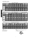
Operating Range
Ensure that the system operates within the application guidelines
shown in the following tables.
Cooling operating range:
Maximum Minimum
DB
_F(_C)
WB
_F(_C)
DB
_F(_C)
WB
_F(_C)
Outdoor Unit
125
(51.7)
---
55
(12.8)
---
Indoor Unit
95
(35)
71
(21.7)
67
(19.4)
57
(13.9)
Heating operating range:
Maximum Minimum
DB
_F(_C)
WB
_F(_C)
DB
_F(_C)
WB
_F(_C)
Outdoor Unit
75
(23.9)
67
(19.4)
---20
(---28.9)
---
Indoor Unit
80
(26.7)
71
(21.7)
55
(12.8)
---
Accessories
An extensive list of field installed accessories is available for both
indoor and outdoor units. Identify what accessories, if any, are
required for the application at hand and consult the separate
installation instructions for the accessories. Some of the
accessories, especially on the indoor units, can be installed much
easier if planned ahead.
INSTALLATION
Complete Pre--installation Checks
1. Unpack Unit -- Store the indoor and outdoor units in the
original packaging until it is moved to the final site for in-
stallation.
2. Inspect Shipment -- Upon receipt of shipment, check the
indoor and outdoor units for damage. If there is any dam-
age, forward claim papers directly to the transportation
company. Manufacturer is not responsible for damage in-
curred in transit.
3. Inspect Parts Supplied With Units – Check all items
against parts list (see page 7). If any items are missing, noti-
fy your distributor or Carrier office. To prevent loss or
damage, leave all parts in original packages until installa-
tion.
Consider System Requirements
1. Consult local building codes and NEC for special installa-
tion requirements.
2. When deciding the location of the indoor and outdoor units,
ensure that the piping run does not exceed the allowed dis-
tances listed in Table 3.
3. Make sure the indoor and outdoor units are easily accessible
to electrical power.
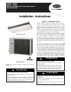
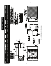
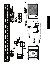
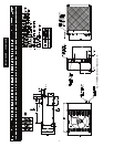
4. Allow sufficient clearances for airflow, wiring, refrigerant
piping, and servicing the unit. See Fig.1 through Fig. 5.
5. Condensate piping can be directed through the inside wall
to an approved drain or straight outside.
INSTALL INDOOR UNIT
Plan the installation carefully before you begin.
1. Select indoor unit location. If possible, place the unit adja-
cent to an outside wall if fresh air is required, and ensure
that the location allows for complete air distribution.
NOTE: If unit is not installed adjacent to an outside
wall and fresh air is required, a power ventilation kit ac-
cessory is available.
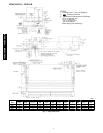
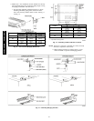
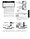
2. Remove the indoor unit from the carton and place it upside
down and perform the following steps:
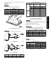
a. Remove side panels by sliding forward, then away from
sides of the unit . See Fig. 9.
A09525
Fig. 9 -- Removal of Mounting Brackets from Indoor Unit
b. Remove air filters from inlet grilles; then remove and
retain screws securing inlet grilles to indoor unit.
c. Remove inlet grilles from indoor unit by sliding for-
ward.
d. If a size 024 indoor unit is to be matched with a size
018 outdoor unit, switch the Molex plug on the motor.
The Molex plugs are labeled as 018 or 024.
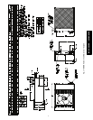
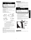
e. Loosen hex bolts on the side of the unit and remove the
mounting brackets by sliding them out in direction
shown in Fig. 10. Allow approximately 3/8 inch space
between the bolt head and the unit as shown in Fig. 10.
A09527
Fig. 10 -- Installing Hex--Head Mounting Bolts
in Fan Coil Unit
f. If piping is going to be run from the right hand side,
open knock--out by removing the pre--split portion in
the rear of the right hand side panel with a saw or cutter
knife.
40QAC/38HDR -- 40QAQ/38QR
R