


13
!
WARNING
ELECTRICAL SHOCK HAZARD
Failure to follow this warning could result in personal injury or
death.
Before performing service or maintenance, be sure indoor unit
main power switch is turned OFF and indoor blower has
stopped.
Lock out and tag switch with suitable warning label.
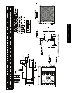
Power Wiring
1. Mount outdoor power disconnect. The unit is factory wired
for the voltage shown on the unit nameplate. The fused dis-
connect switch must be provided within sight of the unit,
readily accessible, but out of reach of children. Provisions
for locking the disconnect switch on the OFF (open) posi-
tion is advisable. The disconnect switch must comply with
NEC and local codes. Protect theunit and wiring using only
the recommended fuse/circuit breaker size. See Table 10..
2. Run power wiring from main box to disconnect per NEC
and local codes.
3. Run power wiring from the disconnect switch to outdoor
unit. Use only minimum 60_C copper conductors between
the disconnect switch and the unit for field power connec-
tion.
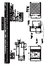
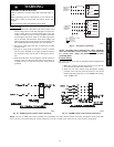
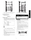
4. Route the field power wires through the conduit connection
opening in the unit side panel and connect in junction box
as shown in Fig 17. The unit and power wiring must be
grounded.
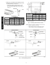
BLK
BLK
SINGLE-PHASE UNIT
GROUNDING LUG
SINGLE-PHASE
CONN TO
DISCONNECT
PER NEC
BLK
BLU
YEL
GROUNDING LUG
THREE-PHASE
CONN TO
DISCONNECT
PER NEC
THREE-PHASE UNIT
GROUND LEAD
GROUND LEAD
LEGEND
NEC -- National Electrical Code
-- Splice (field)
Field Wiring
Factory Wiring
A08251
Fig. 17 -- Line Power Connections
NOTE: Operating unit on improper line voltage constitutes
abuse and could affect Carrier warranty. DO NOT
install unit
in a system where voltage may fluctuate above or below
permissible limits.
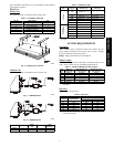
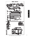
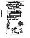
Control Wiring
The control circuit is 24 volts AC (minimum 40VA) supplied from
the indoor unit.
1. Make sure you have enough control wires to cover the dis-
tance between the indoor and outdoor unit.
2. Route one end of the control wiring through the opening
provided in the unit side panel and connect to the control
terminal strip using either Fig. 18 for 38HDR units and Fig.
19 for 38QRR units.
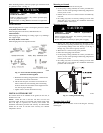
Y1
A09603
Fig. 18 -- 38HDR Typical Control Circuit Connections
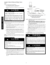
A09509
Fig. 19 -- 38QRR Typical Control Circuit Connections
NOTE: Use No. 18 AWG color--coded, insulated (35_C minimum) wire. If the distance between the indoor and outdoor unit is greater than
100 ft. (30.5 m), as measured along the control voltage wires, use No. 16 AWG color--coded wire to avoid excessive voltage drop.
40QAC/38HDR -- 40QAQ/38QR
R