


12
Complete Outdoor Refrigerant Piping Connec-
tions
Follow the following general guidelines:
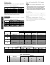
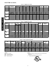
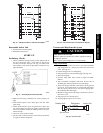
1. Use refrigerant grade field – supplied tubing.
Refer to Table 4 for the correct line sizes.
2. Do not use less than 10 ft (93.05 m) of interconnecting
tubing.
CAUTION
!
UNIT DAMAGE HAZARD
Failure to follow this caution may result in equipment
damage or improper operation.
If any section of pipe is buried, there must be a6 in. (152.4
mm) vertical rise to the valve connections on the outdoor
unit. If more than the recommended length is buried,
refrigerant may migrate to cooler, buried section during
extended periods of system shutdown. This causes
refrigerant slugging and could possibly damage the
compressor at start--up.
When more than 80 ft (24.4 m) of interconnecting tubing is used,
consult the Duct--Free Split System Long Line Application Guide
for required accessories.
3. On cooling only units, insulate the liquid line. On heat
pumps, insulate both lines. A minimum of 1/2 inch foam
pipe insulation is recommended.
4. Run the refrigerant tubes as directly as possible and avoid
unnecessary turns and bends.
5. Suspend refrigerant tubes to avoid damage to insulation or
tubes so they do not transmit vibration to the structure.
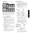
6. When passing refrigerant tubes through the wall, seal the
opening so rain and insects do not enter the structure. Leave
some slack in refrigerant tubes between structure and out-
door unit to absorb vibration.
NOTE: A fusible plug is located in unit suction line; do not cap
this plug. If local codes require additional safety devices, install as
directed.
Connection at Outdoor Unit
CAUTION
!
UNIT DAMAGE HAZARD
Failure to follow this caution may result in equipment damage
or improper operation.
To prevent damage to unit or service valves observe the
following:
S A brazing shield MUST be used.
S Wrap service valves with wet cloth or use a heat sink
material.
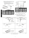
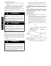
1. Braze the connector tubes (field supplied for the 38HDR
units and factory supplied for the 38QRR units) to the inlet
of the factory supplied filter drier. If a cooling only unit is
being installed move to step 3 (see Fig. 8).
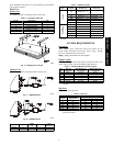
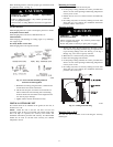
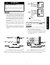
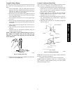
2. Remove the plastic cap from the liquid and suction service
valve on the 38QRR unit and assemble the heating piston
and piston cap supplied with the outdoor unit as shown in
Fig. 16.
NOTE: Teflon Seal must face toward the outdoor heat pump unit.
A09538
Fig. 16 -- AccuRater Metering Device at Service
Valve (Bypass Type Components),
Heat Pump Systems Only
NOTE: The Teflon seal on the piston should point towards the
liquid service valve.
The size of the factory supplied piston might have to
adjusted for long lineapplications (over 80 ft / 24.4 m).
Refer to the Duct Free Long Line Application Guide
for additional information.
3. On 38HDR units, remove the plastic caps on the liquid and
suction service valves. Braze the completed filter drier as-
sembly (from Step 1) to the liquid service valve. On the
38QRR unit, connect the completed filter drier assembly
(from Step 1) to the piston cap.
4. Braze the field supplied line set to the filter drier assembly
andtothesuctionvalve.
5. Insulate any exposed areas between the filter drier and the
liquid valve.
Complete Outdoor Power and Control Wiring
!
WARNING
ELECTRICAL SHOCK HAZARD
Failure to follow this warning could result in personal injury or
death.
The unit cabinet must have an uninterrupted or unbroken
ground to minimize personal injury if an electrical fault should
occur. The ground may consist of electrical wire or metal
conduit when installed in accordance with existing electrical
codes.
CAUTION
!
UNIT DAMAGE HAZARD
Failure to follow this caution may result in equipment damage
or improper operation.
Unit failure as a result of operation on improper line voltage or
excessive phase imbalance constitutes abuse and may cause
damage to electrical components. Such operation could void
any applicable Carrier warranty.
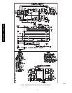
40QAC/38HDR -- 40QAQ/38QR
R