


17
Complete Indoor Piping
The piping to the indoor unit can be routed from the back, side and
top. If the unit is being piped from the top or the side see note
below.
1. On heat 40QAQ024 – 048, the cooling piston (indoor) is
shipped in the factory installed metering device with the in-
door unit. Use Table 6 to verify that you have the correct
piston size for the system being installed.
2. Run the line set and the control wiring from the outdoor to
the indoor unit through thehole in the wall. Keep the piping
general guidelines in mind.
3. Cut the liquid and suction line to the correct length using a
tube cutter.
4. Remove the flare nuts from the indoor piping connections.
Install them onto the liquid and suction lines and make flare
connections.
5. Apply a small amount of refrigerant oil to the flare connec-
tion and tubing.
6. Align the tubing with the refrigerant connections on the in-
door unit.
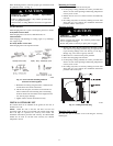
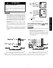
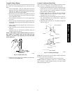
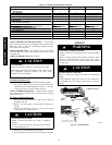
7. Tighten the flare nut and finish the installation using two
wrenches as shown in Fig. 22.
NOTE: When piping is being routed from the top or side, two
pipe adaptors are supplied with the unit. Flare the pipe
adaptors to the indoor unit connections and sweat the other
ends to the line set.
A07354
Fig. 22 -- Tighten Flare Nut
8. Insulate both connections on the 38QRR and the liquid line
connection on the 38HDR units.
Connect Condensate Drain Line
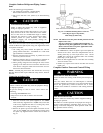
Observe all local sanitary codes when installing condensate drains.
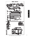
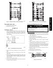
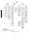
Refer to Fig. 23 for drain pipe connection from indoor unit.
1. Use hard polyvinyl chloride (PVC) pipe material with nom-
inal ID of 3/4 in. to connect at drain line. Use pipe insula-
tion 1/4 in. thick, such as Armaflex insulation, on exposed
piping inside the conditioned space.
2. To insure regular flow of condensate water, the drain pipe
should be pitched toward an open drain or sump at a down-
ward slope of at least 1/4 in. per ft.
3. If the drain piping is routed through the side of the unit, at-
tach a field fabricated piece of sheet metal to support the
drain pipe as shown in Fig. 23.
4. Attach drain pipe with nylon wire tie passing through hole
as shown in Fig. 23.
(Field Fabricated)
A09534
Fig. 23 -- Routing Drain Piping
NOTE: Do not fasten nylon wire ties tight enough to deform the
insulation, as this affects performance.
5. Install an external trap at the end of the condensate line.
NOTE: Should the installation require one, a condensate pump
may be ordered as a fields--installed accessory. It is easier to install
pump before hanging the unit.
40QAC/38HDR -- 40QAQ/38QR
R