


18
Complete Control Wiring
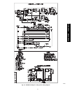
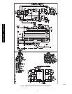
1. Run the control wiring close to the terminal block on the
indoor unit.
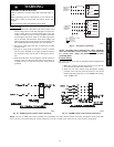
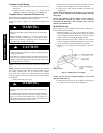
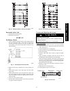
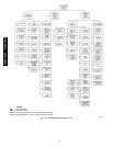
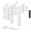
2. Connect the wires as shown in Fig 18 and Fig. 20 for
38HDR units, and Fig. 19 and Fig. 21 for 38QRR units.
Complete Power Connection To Indoor Unit
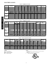
Be sure field wiring complies with local building codes and NEC,
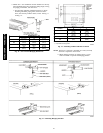
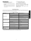
and unit voltage is within limits shown in Table 12.
Contact local power company for correction of improper line
voltage.
!
WARNING
ELECTRICAL SHOCK HAZARD
Failure to follow this warning could result in personal injury
or death.
Before installing, modifying, or servicing system, main
electrical disconnect switch must be in the OFF position.
There may be more than 1 disconnect switch. Lock out and
tag switch with a suitable warning label.
CAUTION
!
UNIT DAMAGE HAZARD
Failure to follow this caution may result in equipment damage
or improper operation.
Unit failure as a result of operation on improper line voltage or
excessive phase imbalance constitutes abuse and may cause
damage to electrical components. Such operation could void
any applicable Carrier warranty.
NOTE: Use copper wire only between disconnect switch(es) and
unit.
NOTE: Install branch circuit disconnect of adequate size to handle
unit starting current per NEC. Locate disconnect within sight of,
and readily accessible from, unit, per section 440--14 of NEC.
Some codes allow indoor unit to share disconnect with outdoor
unit if disconnect can be locked; check local code before installing
in this manner.
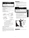
1. Route ground and power wires.
!
WARNING
ELECTRICAL SHOCK HAZARD
Failure to follow this warning could result in personal injury
or death.
According to NEC and most local codes, the unit must have
an uninterrupted, unbroken ground to minimize personal
injury if an electric fault should occur. The ground may
consist of electrical wire or metal conduit when installed in
accordance with existing electrical codes.
2. Route line power leads from inside disconnect to the fan
coil. Place wire through the whole on the control box.
3. Connect wire to high voltage terminal board (TB1) and
ground screw.
NOTE: When routing the wire in the unit, use care to keep the
wire away from refrigerant and condensate piping and any
sharp edges.
NOTE: The 208/230--v units are factory wired for 230--v to
24--v transformer operation, For 208--v to 24--v operation,
interchange the blue (208--v) and red (230--v) wires. Cap any
unused wires with wire nuts.
Install Thermostat
These systems use a three speed thermostat. Refer to Table 9 for a
list of recommended thermostats.
1. Mount thermostat to a wall in the occupied space using
hardware provided with the thermostat. Locate the thermo-
stat, preferably on an interior wall, in an area that is not sub-
jected to drafts or direct sunlight through windows.
2. Run the thermostat wires to the control box of the indoor
unit. If running the thermostat through the back of the unit,
3/8 in. space between the unit and the wall is required.
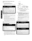
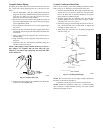
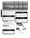
3. Route wires over refrigerant and drain piping as shown in
Fig. 24.
*
Field-supplied.
A09533
Fig. 24 -- Routing Wires Over Piping
NOTE: Do not route wires under the piping, or wires could
impede air filter removal.
4. Connect the thermostat wires to the indoor unit per Fig 25
for a 40QAC unit and Fig. 26 for a 40QAQ unit.
40QAC/38HDR -- 40QAQ/38QR
R