


10
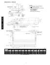
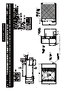
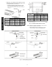
3. Mount Unit -- the installation location should have already
been identified taking into account the piping length, wiring
and piping,connections, and clearances.
a. Use mounting template, included inside box, to locate
mounting bolt holes, piping holes, electrical connec-
tions, and accessory outdoor intake, if used. See Fig. 11
and Fig. 12.
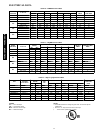
UnitSize
DIMENSIONS in. (cm)
A B C
024
50---15/16
(129.4)
46
(116.8)
49---5/8
(126.0)
036
58---13/16
(149.4)
53---7/8
(136.8)
57---1/2
(146.1)
048
71---9/16
(181.8)
66---5/8
(169.2)
70---1/4
(178.4)
060
92
(233.7)
87
(221)
90---5/8
(230.2)
A09528
Fig. 11 -- Fan Coil Unit Hanging Dimensions
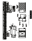
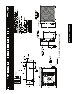
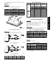
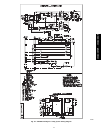
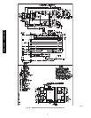
UnitSize
DIMENSIONS in. (cm)
B C
024
46
(116.8)
49---5/8
(126.0)
036
53---7/8
(136.8)
57---1/2
(146.1)
048
66---5/8
(169.2)
70---1/4
(178.4)
060
87
(221)
90---5/8
(230.2)
* --- Concealedmountingh oles
{ --- Exposed mounting holes.
A09046
Fig. 12 -- Mounting Included with Fan Coil Unit
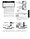
NOTE: If fresh air is required, a minimum of 3 inch (76.2 mm)
clearance is required in back of unit.
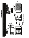
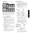
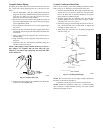
b. Mount hanging brackets on ceiling (see Fig. 13) for
either concealed or exposed bolt hanging position.
A09530
Fig. 13 -- Mounting Hanging Brackets
40QAC/38HDR -- 40QAQ/38QR
R