


21
OPERATING SEQUENCE
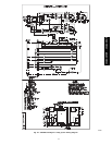
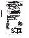
Ceiling--suspended fan coil units have a relay board which controls
system operation in response to a room thermostat. The user may
manually select any one of 3 fan speeds for unit operation. The
discharge louvers on the unit can be stationary or swing
continuously. A switch located at the bottom of the unit will turn
the swing function on and off.
Ceiling--suspended systems may be equipped with an accessory
power ventilation kit and/or condensate pump.
FAN OPERATION — Fan coils are capable of 3--speed
operation. See thermostat instructions for fan speed selection.
When the fan(s) is operating in medium or high speed and the unit
is equipped with the power ventilation kit, the ventilation fan will
operate to provide fresh air.
COOLING MODE OPERATION — When the room thermostat
senses a demand for cooling, the fan coil relay board is energized.
The indoor fan(s) will start in the selected speed (if it is not already
operating). The reversing valve (heat pump only) will energize for
cooling operation.
The internal condensate pump (if so equipped) runs whenever the
reversing valve is energized (heat pump only) and/or the unit is in
cooling. As long as the condensate float switch and freeze
protection thermostat are closed, the cooling relays in the fan coil
unit will close. This energizes the compressor and outdoor fan in
the outdoor unit.
The compressor will continue to operate until the room thermostat
is satisfied. When the cooling demand is satisfied, the compressor
and outdoor fan will stop. If the system is in the AUTO. position,
the indoor fan will stop with the compressor.
If the unit has the accessory ventilation kit, the ventilation fan will
operate whenever the indoor fan is set for medium or high speed.
HEAT PUMP OPERATION — When the room thermostat
senses a demand for heating the indoor fan will start in the selected
speed (if not already operating), and the reversing valve will not be
energized.
The internal condensate pump (if supplied) and freeze protection
thermostat are not operated during heating operation. The control
relay (CR2) closes, and the compressor and outdoor fan are
energized through the defrost board (DFB), which is located in the
outdoor unit. The microprocessor logic in the DFB is energized
when the compressor starts, and the defrost timer runs. Once every
90 minutes (factory default setting) of compressor run time, the
DFB logic checks the defrost thermostat (DFT). If the DFT is
open, the unit continues in heating operation. If the DFT is closed,
the DFB switches the unit to defrost mode. The timing on the DFB
may be set at either 30, 50, or 90 minutes.
DEFROST (Heat Pump Only) — The DFB energizes the RVS
(reversing valve solenoid), and the reversing valve switches to the
cooling position. The K1 relay on the DFB opens and the outdoor
fan stops. The W2 contact on the DFB is also energized, which in
turn energizes the defrost relay on the fan coil relay board, turnsoff
the electric heater and stops the indoor fan.
The DFB logic checks the 10--minute defrost timer and the DFT. If
the DFT opens in less than 10 minutes, the DFB switches the unit
back to normal heating operation. If the DFT remains closed, the
DFB switches the unit back to heating operation after 10 minutes.
When the DFB changes back to heating mode, the RVR (reversing
valve relay) is de--energized and the reversing valve switches back
to heating operation. Both the outdoor and indoor fans come back
on, and if necessary, the electric heater also turns on. SYSTEM
SAFETIES — The system is equipped with the following safety
devices to protect system components: Indoor coil freeze
protection thermostat — If a coil temperature of 28_F (--2.22_C) or
lower is sensed, the compressor and outdoor fan will be shut down
until the coil temperature exceeds 28_F (--2.22_C). The indoor fan
will continue to run. Condensate float switch (units equipped with
accessory condensate pump, cooling cycle only) — If the level of
condensate in the drain pan rises too high, the condensate float
switch will turn the system off.
CLEANING AND MAINTENANCE
!
WARNING
ELECTRICAL SHOCK HAZARD
Failure to follow this warning could result in personal
injury or death.
Before installing, modifying, or servicing system, main
electrical disconnect switch must be in the OFF
position. There may be more than 1 disconnect switch.
Lock out and tag switch with a suitable warning label.
CAUTION
!
UNIT DAMAGE HAZARD
Failure to follow this caution may result in equipment
damage or improper operation.
To avoid shrinkage, do not wash filter in water over
120_F (48.9_C). To avoid damage, do not expose filter to
fire or direct sunlight . Clean the filter more frequently
when air is extremely dirty.
For proper system operation, perform the cleaning and
maintenance operations in Table 13.
Lubrication — The indoor--fan, automatic air sweep, and the
outdoor--fan motors are factory lubricated and require no oiling.
AIR FILTERS
CAUTION
!
UNIT DAMAGE HAZARD
Failure to follow this caution may result in equipment
damage or improper operation.
Operating the system with dirty air filters may damage the
indoor unit and can cause reduced cooling performance,
intermittent system operation, frost build--up on the indoor
coil, and blown fuses. Inspect and clean or replace the air
filters monthly.
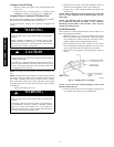
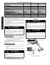
REMOVE AIR FILTERS — Remove filters by pulling them
straight out.
CLEAN OR REPLACE FILTERS — Filters can be vacuumed
or washed in warm water. Shake filter to remove any excess water,
and replace by sliding filter behind grille until filter snaps in place.
Refer to Fig. 32. If the filter has begun to break down or is torn,
replace it. Replacement filters are available through your dealer.
40QAC/38HDR -- 40QAQ/38QR
R