


6
Step 4 — Make Electrical Connections
CONTROL CIRCUIT WIRING — Control voltage is 24 v
(40 va minimum). See Fig. 5 and unit label diagram for field-
supplied wiring details. Route control wire through opening in
unit side panel to connection in unit control box.
NOTE: For wire runs up to 50 ft, use no. 18 AWG (American
Wire Gage) insulated wire. For 50 to 75 ft, use no. 16 AWG
insulated wire. For over 75 ft, use 14 AWG insulated wire.
NOTE: All wiring must conform to NEC and local codes.
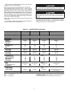
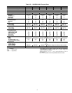
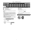
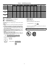
NOTE: Operating unit on improper line voltage constitutes
abuse and could affect Carrier warranty. See Tables 2 and 3.
Do not install unit in a system where voltage may fluctuate
above or below permissible limits.
See Tables 2 and 3 for recommended fuse sizes. When mak-
ing electrical connections, provide clearance at the unit for re-
frigerant piping connections.
NOTE: The 38HDF units are supplied with a 24-v control
transformer. The 38HDR units use the control transformer
supplied with the matched indoor unit.
POWER WIRING — Unit is factory wired for voltage shown
on nameplate. Provide adequate, fused disconnect switch
within sight from unit, readily accessible, but out of reach of
children. Provision for locking the switch open (off) is advis-
able to prevent power from being turned on while unit is being
serviced. Disconnect switch, fuses, and field wiring must
comply with the NEC and local code requirements. Use copper
wire only between the disconnect switch and unit. Use
minimum 60 C wire for the field power connection.
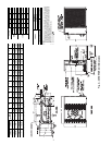
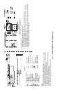
Route power wires through the opening in unit side panel
and connect in the unit control box as shown on the unit label
diagram and Fig. 6 and 7. Unit must be grounded.
CONNECTIONS TO DUCT-FREE FAN COIL UNITS —
The 38HDR units are designed for easy match-up to 40QA
duct free fan coils. This unit provides 24 v power for the out-
door unit from the fan coil. Connect the Y and C terminals of
the indoor unit to the Y and C terminals.
Unit cabinet must have an uninterrupted, unbroken electri-
cal ground to minimize the possibility of personal injury if
an electrical fault should occur. This ground may consist of
electrical wire connected to unit ground lug in control com-
partment, or conduit approved for electrical ground when
installed in accordance with NEC, and local electrical
codes. Failure to follow this warning could result in the
installer being liable for the personal injury of others.
Unit failure as a result of operation on improper line
voltage or excessive phase imbalance constitutes abuse and
may cause damage to electrical components. Such opera-
tion would invalidate any applicable Carrier warranty.
Before performing service or maintenance, be sure indoor
unit main power switch is turned OFF and indoor blower
has stopped. Failure to do so may result in electrical shock
or injury from rotating fan blades.
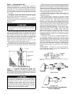
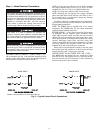
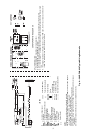
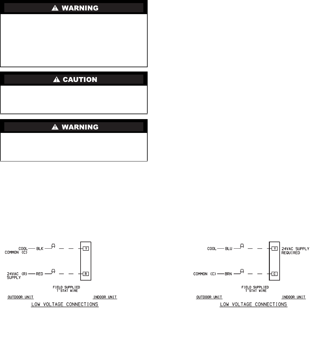
38HDF UNITS
38HDR UNITS
NOTE: For more information see schematic inside unit.
Fig. 5 — Typical Control Circuit Connections