


4
Only use factory specified liquid-line filter driers with rated
working pressures less than 600 psig.
NOTE: Do not install a suction-line filter drier in liquid line.
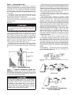
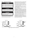
MAKE PIPING SWEAT CONNECTIONS — Remove plastic
caps from liquid and suction service valves. Use refrigerant
grade tubing. Service valves are closed from the factory and are
ready for brazing. After wrapping the service valve with a wet
cloth, the tubing set can be brazed to the service valve using ei-
ther silver bearing or non-silver bearing brazing material. Con-
sult local code requirements. Refrigerant tubing and the indoor
coil are now ready for leak testing.
NOTE: Unit is shipped with R-410A factory charge indicated
on nameplate.
Pass nitrogen or other inert gas through piping while braz-
ing to prevent formation of copper oxide.
PROVIDE SAFETY RELIEF — A fusible plug is located in
unit suction line; do not cap this plug. If local code requires
additional safety devices, install as directed.
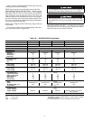
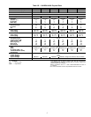
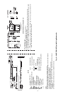
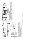
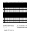
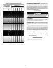
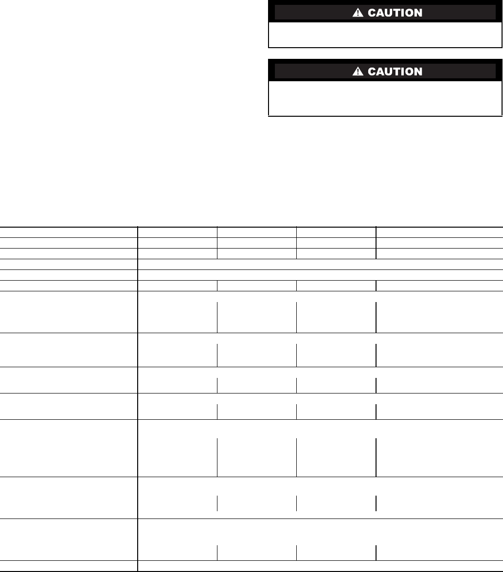
Table 1A — 38HDF018-036 Physical Data
LEGEND *Unit shipped with full factory charge. See ARI (Air Conditioning and
Refrigeration Institute) capacity table for proper charge and piston
for each fan coil type.
†24 v and a minimum of 40 va is provided in the fan coil unit.
To avoid damage while brazing, service valves should be
wrapped with a heat-sinking material such as a wet cloth.
When brazing tubing sets to the service valves, a brazing
shield MUST be used to prevent damage to the painted unit
surface.
UNIT 38HDF 018 024 030 036
NOMINAL CAPACITY (Tons) 1.5 2.0 2.50 3.0
OPERATING WEIGHT (lb) 166 176 187 250
REFRIGERANT TYPE R-410A
METERING DEVICE AccuRater (Located at Fan Coil)
CHARGE (lb)* 4.8 5.3 5.0 7.1
OUTDOOR FAN
Rpm/Cfm 840/1720 840/1720 840/1720 850/1720
Diameter (in.) 18 18 18 24
No. Blades 333 3
Motor (hp)
1
/
8
1
/
8
1
/
8
1
/
4
OUTDOOR COIL
Face Area (sq ft) 5.82 7.27 7.27 12.1
No. Rows 233 2
FPI 20 20 20 20
HIGH PRESSURE SWITCH
Cut-In (psig) 420 ± 25 420 ± 25 420 ± 25 420 ± 25
Cutout (psig) 650 ± 10 650 ± 10 650 ± 10 650 ± 10
LOW PRESSURE SWITCH
Cut-In (psig) 45 ± 25 45 ± 25 45 ± 25 45 ± 25
Cutout (psig) 20 ± 5 20 ± 5 20 ± 5 20 ± 5
REFRIGERANT LINES
Connection Type Sweat
Liquid Line (in.) OD
3
/
8
3
/
8
3
/
8
3
/
8
Vapor Line (in.) OD
5
/
8
5
/
8
3
/
4
3
/
4
Max Length (ft) 200 200 200 200
Max Lift (ft) 65 65 65 65
Max Drop (ft) 150 150 150 150
COMPRESSOR
Type Scroll
Model ZP16K5E-PFV ZP21K5E-PFV ZP25K5E-PFV ZP34K5P-PFV
Oil Charge (POE - oz) 25.0 25.0 25.0 42.0
Accumulator Ye s
CONTROLS
Fusible Plug (F) 210
Control Voltage† 24 vac
System Voltage 208/230 v 208/230 v 208/230 v
208/230 v, Single and 3 Phase,
460 v, 3 Phase
FINISH Gray
FPI — Fins Per Inch
POE — Polyol Ester