


11
START-UP
Preliminary Checks
1. Check that all internal wiring connections are tight and
that all barriers, covers, and panels are in place.
2. Field electrical power source must agree with unit name-
plate rating.
3. All service valves must be open.
4. Belly-band crankcase heater must be tight on compressor
crankcase for those units with belly-band heaters.
Leak Test — Fieldpipingandfancoilmustbeleaktested
by pressure method. Use R-410A at approximately 25 psig
backed up with an inert gas to a total pressure not to exceed
245 psig.
Leak detectors should be designed to detect HFC (hydro-
fluorocarbon) refrigerant.
Evacuate and Dehydrate — Fieldpipingandfancoil
must be evacuated and dehydrated.
Charge System — Release charge into system by open-
ing (backseating) liquid and suction line service valves. Refer
to separate indoor unit installation instructions for the required
total system charge when connected to 25 ft of tubing.
To Start Unit — Be sure that the field disconnect is
closed. Set room thermostat below ambient temperature. Oper-
ate unit for 15 minutes, then check system refrigerant charge.
See Refrigerant Charging section on page 12.
NOTE: When using in conjunction with 40QA or 40QK fan
coils, refer to start-up instructions included with fan coil for
correct start-up procedures.
SERVICE
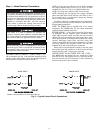
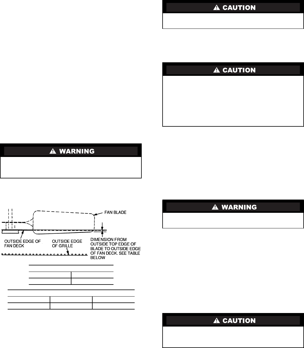
Outdoor Fan — A reinforced wire mount holds the out-
door fan assembly in position. See Fig. 8 for proper mounting
position.
High-Pressure Relief Valve — The high-pressure re-
lief valve is located in the compressor. The relief valve opens at
a pressure differential of approximately 550 to 625 ± 50 psid
between suction (low side) and discharge (high side) to allow
pressure equalization.
Internal Current and Temperature Sensitive
Overload —
The control resets automatically when
internal compressor motor temperature drops to a safe level
(overloads may require up to 45 minutes to reset). When an
internal overload is suspected of being open, check by using an
ohmmeter or continuity tester.
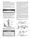
Pumpdown Procedure — The system may be pumped
down in order to make repairs on the low side without losing
complete refrigerant charge.
When system must be opened for service, recover refriger-
ant, break vacuum with dry nitrogen before opening system.
1. Attach pressure gage to suction service valve gage port.
2. Frontseat the liquid/mixed phase line valve.
3. Start unit and run until suction pressure reaches 20 psig.
4. Shut unit off and frontseat suction valve.
5. Depressurize low side of unit and recover refrigerant
following accepted practices.
High-Pressure Switch — The high-pressure switch,
located on discharge line, protects against high discharge
pressures caused by such events as overcharge, condenser-fan
motor failure, system restriction, etc. It opens on pressure rise at
about 650 ± 10 psig. If system pressures go above this setting
during abnormal conditions, the switch opens.
The high-pressure switch is checked with an ohmmeter. If
system pressure is below 625 psig switch shows continuity.
Crankcase Heater — The crankcase heater prevents
refrigerant migration and compressor oil dilution during
shutdown when compressor is not operating. If the crankcase
heater is deenergized for more than 6 hours, both compressor
service valves must be closed.
NOTE: Crankcase heaters are only available on 38HDR030-
060 units.
The crankcase heater is powered by the high-voltage power
of the unit. It is connected across the line side of the contactor
and is thermostatically controlled.
Before performing recommended maintenance, be sure
unit main power switch is turned off. Failure to do so may
result in electrical shock or injury from rotating fan blade.
Never open system to atmosphere while it is under a vac-
uum. Equipment damage may result.
The 38HDC unit coils hold only the factory-designated
amount of refrigerant. Additional refrigerant may cause
units to relieve pressure through the compressor internal
pressure relief valve (indicated by a sudden rise of suction
pressure) before suction pressure reaches 5 psig. If this
occurs, shut off unit immediately then frontseat the suction
valve and remove and recover excess refrigerant following
accepted practices. Equipment damage may result.
DO NOT attempt to simulate these system abnormalities
— high pressures pose a serious safety hazard.
Use extreme caution when troubleshooting this device, as
line voltage is continually present. Serious personal injury
could result.
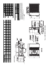
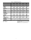
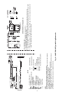
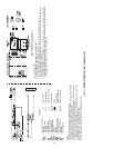
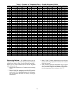
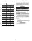
Fig. 8 — Condenser-Fan Mounting Positions
38HDF UNIT SIZE, in.
018-030 036
0.433 0
38HDR UNIT SIZE, in.
018,024 030,036 048,060
0.433 0 0