


3
Step 2 — Rig and Mount Unit
MOUNTING ON GROUND — Mount unit on a solid, level
concrete pad. Position unit so water or ice from roof does not
fall directly onto unit. Accessory stacking kits can be used
when units are to be stacked. See installation instructions
provided with the accessory kit. Use field-provided snow stand
or ice rack where prolonged subfreezing temperatures or heavy
snow occurs.
If conditions or local codes require unit be fastened to a pad,
6 field-supplied tiedown bolts should be used and fastened
through slots provided in unit mounting feet.
MOUNTING ON ROOF — Mount unit on a level platform
or frame at least 6 in. above roof surface. Isolate unit and tub-
ing from structure.
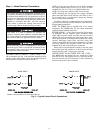
RIGGING
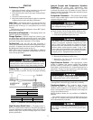
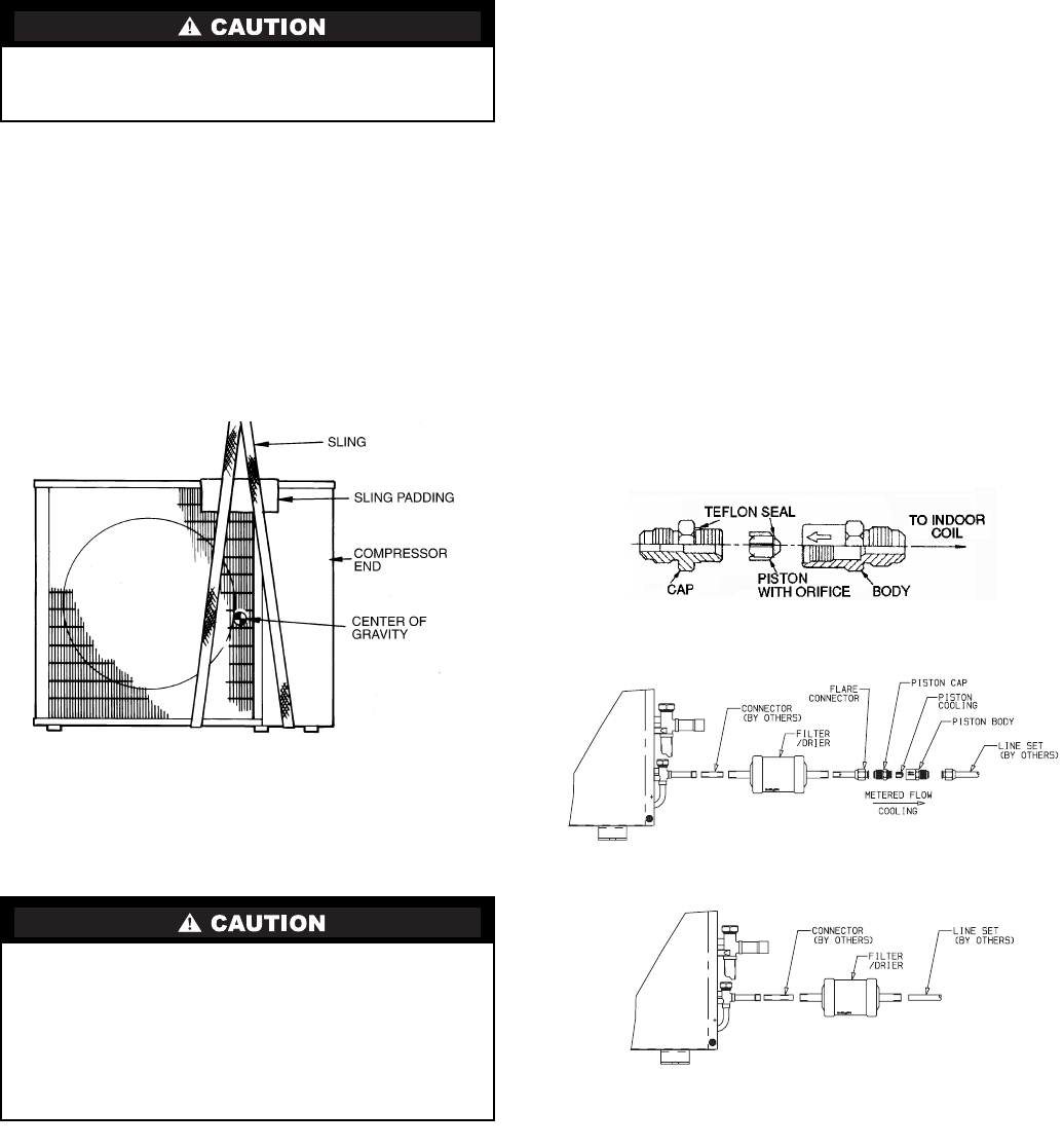
Keep the unit upright and lift unit using a sling. Use card-
board or padding under the sling, and spreader bars to prevent
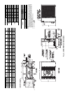
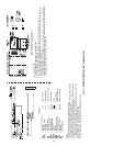
sling damage to the unit. See Fig. 3. See Fig. 2 for center of
gravity reference. Install the unit so that the coil does not face
into prevailing winds. If this is not possible and constant winds
above 25 mph are expected, use accessory wind baffle. See
installation instructions provided with the accessory kit.
NOTE: Accessory wind baffles should be used on all units
with accessory low ambient temperature control.
Field-fabricated snow or ice stands may be used to raise unit
when operation will be required during winter months. Units
may also be wall mounted using the accessory wall-mounting
kit.
Step 3 — Complete Refrigerant Piping Con-
nections —
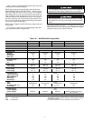
Outdoor units may be connected to indoor
units using field-supplied tubing of refrigerant grade and condi-
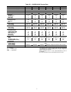
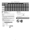
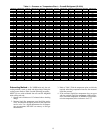
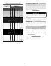
tion. See Tables 1A and 1B for correct line sizes. Do not use
less than 10 ft of interconnecting tubing.
When more than 50 ft of interconnecting tubing and more
than 30 ft of vertical lift is used, consult the residential long line
application instruction guide. For long-line applications, inter-
connecting lines over 100 ft must be installed with a liquid line
solenoid. A liquid line solenoid may also be installed on some
units to improve part-load efficiency. Refer to the ARI (Air
Conditioning & Refrigeration Institute) Directory.
If either refrigerant tubing or indoor coil is exposed to
the atmosphere, the system must be evacuated following good
refrigeration practices.
Run refrigerant tubes as directly as possible, avoiding
unnecessary turns and bends. Suspend refrigerant tubes so they
do not damage insulation on vapor tube and do not transmit
vibration to structure. Also, when passing refrigerant tubes
through a wall, seal the opening so that vibration is not transmit-
ted to structure. Leave some slack in refrigerant tubes between
structure and outdoor unit to absorb vibration. Refer to separate
indoor unit installation instructions for additional information.
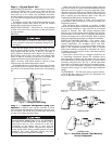
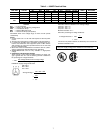
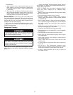
CHECK ACCURATER CONTROL — The correct Accu-
Rater (bypass type) refrigerant control is required for system
capacity optimization. An AccuRater device with field-
replaceable piston (see Fig. 4) is supplied with the outdoor unit.
Refer to the AccuRater metering device table in separate
indoor unit installation instructions to determine the correct
AccuRater piston size required for the condenser/evaporator
system being installed.
Piston style as shown in Fig. 4 is shipped with the unit. Do
not interchange components between the AccuRater device
types. Matching of outdoor unit with indoor unit may require
field replacement of piston. Replace piston, if required, before
connecting refrigerant lines. See Fig. 4. Piston replacement
instructions are included in the indoor unit installation instruc-
tions. After system installation is complete, see the Refrigerant
Charging section on page 12 to check and/or adjust refrigerant
charge.
FILTER DRIER — The filter drier must be replaced whenev-
er the refrigeration system is exposed to the atmosphere. See
Fig. 4 for filter drier installation.
Be sure unit panels are securely in place prior to rigging.
Loose unit panels could result in equipment damage or per-
sonal injury.
DO NOT BURY MORE THAN 36 IN. OF REFRIGER-
ANT PIPE IN THE GROUND. If any section of pipe is
buried, there must be a 6-in. vertical rise to the valve
connections on the outdoor unit. If more than the
recommended length is buried refrigerant may migrate to
cooler, buried section during extended periods of system
shutdown. This causes refrigerant slugging and could
possibly damage the compressor at start-up.
Fig. 3 — Lifting Unit with Sling
NOTE: Arrow on AccuRater body points in free flow direction, away from the
indoor coil.
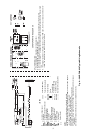
38HDF018-036
38HDR018-060
Fig. 4 — AccuRater (Bypass Type) Metering
Device Components