


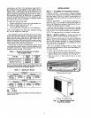

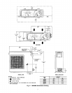
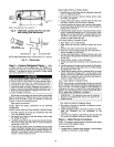
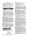
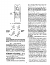
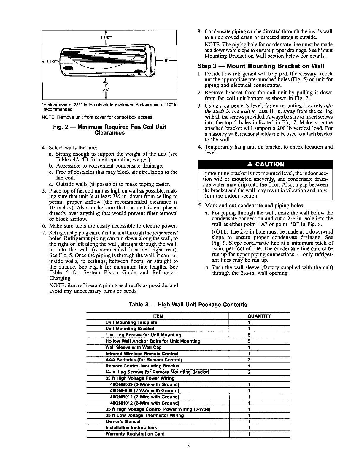
m 8 "....._
+
36"
*Aclearanceof31,_"istheabsoluteminimum.Aclearanceof10"is
recommended.
NOTE: Remove unitfront cover for controlbox access.
Fig. 2 -- Minimum Required Fan Coil Unit
Clearances
4. Select walls that are:
a. Strong enough to support the weight of the unit (see
Tables 4A-4D for unit operating weight).
b. Accessible to convenient condensate drainage.
c. Free of obstacles that may block air circulation to the
fan coil.
d. Outside walls (if pussible) to make piping easier.
5. Place top of fan coil unit as high on wall as possible, mak-
ing sure that unit is at least 31Ain. down from ceiling to
permit proper airflow (the recommended clearance is
10 inches). Also, make sure that the unit is not placed
directly over anything that would prevent filter removal
or block airflow.
6. Make sure units are easily accessible to electric power.
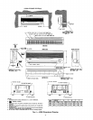
7. Refrigerant piping can enter tbe unit through the prepunched
holes. Refrigerant piping can run down along the wall, to
the right or lef_ along the wall, straight through the wall,
or into the wall (recommended location: right rear).
See Fig. 5. Once the piping is through the wall, it can run
inside walls, in ceilings, between floors, or straight to
the outside. See Fig. 6 for maximum line lengths. See
Table 5 for System Piston Guide and Refrigerant
Charging.
NOTE: Run refrigerant piping as directly as possible, and
avoid any unnecessary turns or bends.
8. Condensate piping canbe directed through the inside wall
to an approved drain or directed straight outside.
NOTE: The piping hole for condensate line must be made
at a downward slope to ensure proper drainage. See Mount
Mounting Bracket on Wall section below for details.
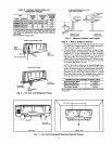
Step 3 -- Mount Mounting Bracket on Wall
l. Decide how refrigerant will be piped. If necessary, knock
out the appropriate pre-puncbed holes (Fig. 5) on unit for
piping and electrical connections.
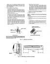
2. Remove bracket from fan coil nnit by pulling it down
from fan coil unit bottom as shown in Fig. 7.
3. Using a carpenter's level, fasten mounting brackets into
the studs in the wall at least 10 in. away from the ceiling
with all the screws provided. Always be sure to insert screws
into the top 2 holes indicated in Fig. 7. Make sure the
attached bracket will support a 200 lb vertical load. For
a masonry wall, anchor shields can be used to attach bracket
to the wall.
4. Temporarily hang unit on bracket to check location and
level.
I_] [,,"_lii[.] _"I
If mounting bracket is not mounted level, the indoor sec-
tion will be mounted unevenly, and condensate drain-
age water may drip onto the floor. Also, a gap between
thebracket and the wall may result in vibration and noise
from the indoor section.
5.
Mark and cut condensate and piping holes.
a. For piping through the wall, mark the wall below the
condensate connection and cut a 2V2-in. hole into the
wall at either point "A" or point "B" in Fig. 8.
NOTE: The 2V2-in hole must be made at a downward
slope to ensure proper condensate drainage. See
Fig. 9. Slope condensate line at a minimum pitch of
1/4in. per foot of line. The condensate line cannot be
run up for upper piping connections -- only refriger-
ant lines may be run up.
b. Push the wall sleeve (factory supplied with the unit)
through the 2]/2-in. wall opening.
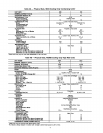
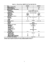
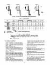
Table 3 -- High Wall Unit Package Contents
ITEM QUANTITY
Unit Mounting Template 1
Unit Mounting Bracket 1
1-in. Lag Screws for Unit Mounting 8
Hollow Wall Anchor Bolls for Unit Mounting 5
Wall Sleeve with Wall Cap 1
Infrared Wireless Remote Control 1
AAA Batteries (for Remote Control) 2
Remote Control Mounting Bracket 1
3/n-in. Lag Screws for Remote Mounting Bracket 2
35 ff High Voltage Power Wiring
40QNB009 (3-Wiro with Ground) 1
40QNE009 (2-Wire with Ground) 1
40QNB012 (2-Wire with Ground) 1
40QNH012 (2-Wiro with Ground) 1
35 ft High Voltage Control Power Wiring (3-Wire) 1
35 ft Low Voltage Thermistor Wiring 1
Owner's Manual 1
Installation Instructions 1
Warranty Registration Card 1