


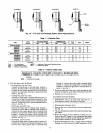
INCORRECT
6
6
b
INCORRECT INCORRECT
CORRECT
P,
6
6
_WALL
UNIT DRAIN
"_-_'-" PIPING
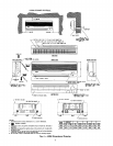
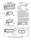
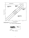
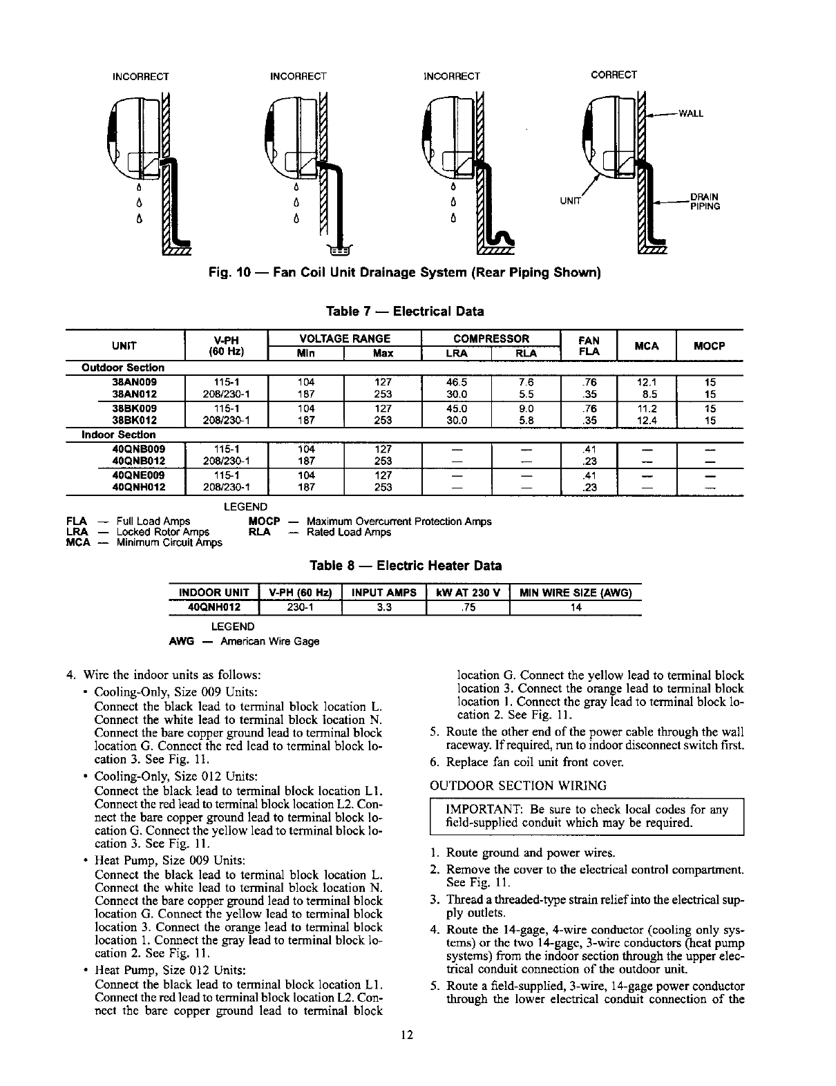
Fig. 10 -- Fan Coil Unit Drainage System (Rear Piping Shown)
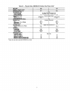
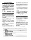
Table 7 -- Electrical Data
UNiT
Outdoor Section
38AN009
38AN012
38BK009
38BK012
Indoor Section
40QNB009
40QNB012
40QNE009
40QNH012
I V-PH [ VOLTAGERANGE [
(60Hz) Min I Max
11_1 t 104 127 t 46.5
208/230-1 187 253 30.0
115-1 104 127 45.0
208/23_1 187 253 30.0
104
187
104
187
127 t --
253
127
253
115-1
20_23_1
20_23_1
COMPRESSOR FAN MCA
LRA I RLA FLA
7.6 .76 12.1
5.5 ._
0.0
5.8
MOCP -- Maximum Overcurrent Protection Amps
RLA -- Rated Load Amps
LEGEND
FLA -- Full Load Amps
LRA -- Locked Rotor Amps
MCA -- Minimum Circuit Amps
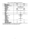
Table 8 -- Electric Heater Data
INDOOR UNIT I V-PH (60 Hz)
40QNH012 I 230-1
LEGEND
AWG -- AmedcanWire Gage
INPUT AMPS kWAT 230 V MINWIRE SIZE (AWG)
3.3 .75 14
MOCP
15
15
15
15
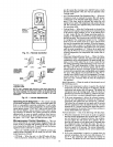
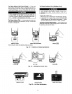
4. Wire the indoor units as follows:
• Cooling-Only, Size 009 Units:
Connect the black lead to terminal block location L.
Connect the white lead to terminal block location N.
Connect the bare copper ground lead to terminal block
location G. Connect the red lead to terminal block lo-
cation 3. See Fig. 11.
• Cooling-Only, Size 012 Units:
Connect the black lead to terminal block location L1.
Connect the red lead to terminal block location L2. Con-
nect the bare copper ground lead to terminal block lo-
cation G. Connect the yellow lead to terminal block lo-
cation 3. See Fig. 11.
• Heat Pump, Size 009 Units:
Connect the black lead to terminal block location L.
Connect the white lead to terminal block location N.
Connect the bare copper ground lead to terminal block
location G. Connect the yellow lead to terminal block
location 3. Connect the orange lead to terminal block
location 1. Connect the gray lead to terminal block lo-
cation 2. See Fig. 11.
• Heat Pump, Size 012 Units:
Connect the black lead to terminal block location L1.
Connect the red lead to terminal block location L2. Con-
nect the bare copper ground lead to terminal block
location G. Connect the yellow lead to terminal block
location 3. Connect the orange lead to terminal block
location 1. Connect the gray lead to terminal block lo-
cation 2. See Fig. 11.
5. Route the other end of the power cable through the wall
raceway. If required, run to indoor disconnect switch first.
6. Replace fan coil unit front cover.
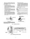
OUTDOOR SECTION WIRING
IMPORTANT: Be sure to check local codes for any
fiald-supplied conduit which may be required.
1. Route ground and power wires.
2. Remove the cover to the electrical control compartment.
See Fig. 11.
3. Thread a threaded-type sWain relief into the electrical sup-
ply outlets.
4. Route the 14-gage, 4-wire conductor (cooling only sys-
tems) or the two 14-gage, 3-wire conductors (heat pump
systems) from the indoor section through the upper elec-
trical conduit connection of the outdoor unit.
5. Route a field-supplied, 3-wire, 14-gage power conductor
through the lower electrical conduit connection of the
12