


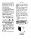
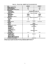
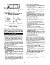
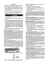
FAN COIL
0 o2-P,
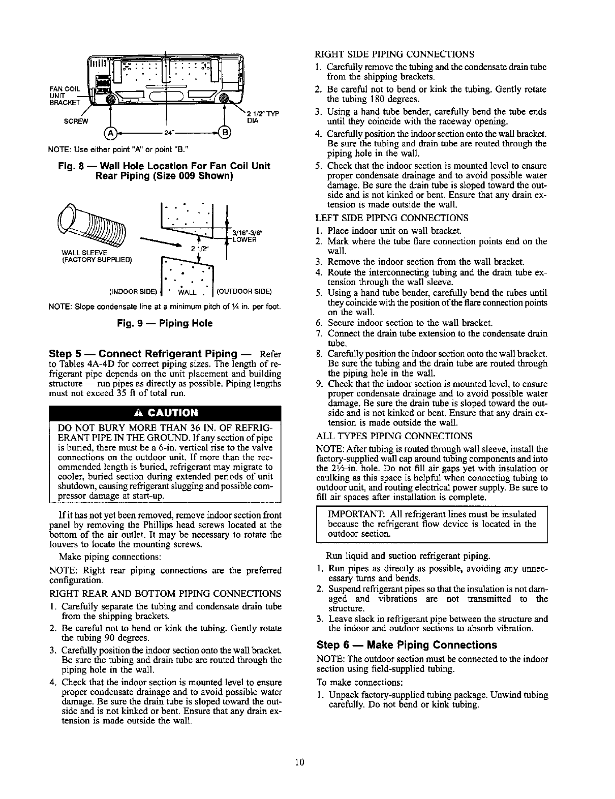
UNIT
/
SCREW
NOTE: Use either point "A"or point "B."
J
_2 W_TYP
DIA
Fig. 8 -- Wall Hole Location For Fan Coil Unit
Rear Piping (Size 009 Shown)
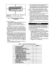
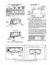
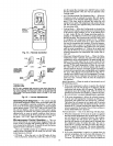
-." i ":
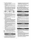
(INDOORSIDE) I " WALL . I (OUTDOOR SIDE)
NOTE:Slopecondensatelineat a minimumpitchof% in.perfoot.
Fig. 9 -- Piping Hole
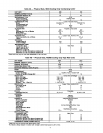
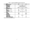
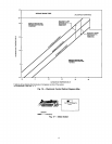
Step 5 -- Connect Refrigerant Piping -- Refer
to Tables 4A-4D for correct piping sizes. The length of re-
frigerant pipe depends on the unit placement and building
structure -- run pipes as directly as possible. Piping lengths
must not exceed 35 ft of total run.
I_?q[,]E_lldIi]_
DO NOT BURY MORE THAN 36 IN. OF REFRIG-
ERANT PIPE IN THE GROUND. lfany section of pipe
is buried, there must be a 6-in. vertical rise to the valve
connections on the outdoor unit. If more than the rec-
ommended length is buried, refrigerant may migrate to
cooler, buried section during extended periods of unit
shutdown, causing refrigerant slugging and possible com-
pressor damage at start-up.
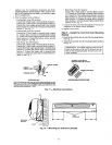
If it has not yet been removed, remove indoor section front
panel by removing the Phillips head screws located at the
bottom of the air outlet. It may be necessary to rotate the
louvers to locate the mounting screws.
Make piping connections:
NOTE: Right rear piping connections are the preferred
configuration.
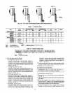
RIGHT REAR AND BOTTOM PIPING CONNECTIONS
1. Carefully separate the tubing and condensate drain tube
from the shipping brackets.
2. Be careful not to bend or kink the tubing. Gently rotate
the tubing 90 degrees.
3. Carefully p°siti°n the ind°°r secti°n °nt° the wail bracket"
Be sure the tubing and drain tube are routed through the
piping hole in the wall.
4. Check that the indoor section is mounted level to ensure
proper condensate drainage and to avoid possible water
damage. Be sure the drain tube is sloped toward the out-
side and is not kinked or bent. Ensure that any drain ex-
tension is made outside the wall.
RIGHT SIDE PIPING CONNECTIONS
1. Carefully remove the tubing and the condensate drain tube
from the shipping brackets.
2. Be careful not to bend or kink the tubing. Gently rotate
the tubing 180 degrees.
3. Using a hand tube bender, carefully bend the tube ends
until they coincide with the raceway opening.
4. Carefully position the indoor section onto the wall bracket.
Be sure the tubing and dram tube are routed through the
piping hole in the wall.
5. Check that the indoor section is mounted level to ensure
proper condensate drainage and to avoid possible water
damage. Be sure the drain tube is sloped toward the out-
side and is not kinked or bent. Ensure that any drain ex-
tension is made outside the wall.
LEFT SIDE PIPING CONNECTIONS
1. Place indoor unit on wall bracket.
2. Mark where the tube flare connection points end on the
wall.
3. Remove the indoor section from the wall bracket.
4. Route the interconnecting tubing and the drain tube ex-
tension through the wall sleeve.
5. Using a hand tube bender, carefully bend the tubes until
they coincide with the position of the flare connection points
on the wall.
6. Secure indoor section to the wall bracket.
7. Connect the drain tube extension to the condensate drain
tube.
8. Carefully position the indoor section onto the wall bracket.
Be sure the tubing and the drain tube are routed through
the piping hole in the wall.
9. Check that the indoor section is mounted level, to ensure
proper condensate drainage and to avoid possible water
damage. Be sure the drain tube is sloped toward the out-
side and is not kinked or bent. Ensure that any drain ex-
tension is made outside the wall.
ALL TYPES PIPING CONNECTIONS
NOTE: After tubing is routed through wall sleeve, install the
factory-supplied wall cap around tubing components and into
the 2V2-in. hole. Do not fill air gaps yet with insulation or
caulking as this space is helpful when connecting tubing to
outdoor unit, and routing electrical power supply. Be sure to
fill air spaces ailer installation is complete.
IMPORTANT: All refrigerant lines must be insulated
because the refrigerant flow device is located in the
outdoor section.
Run liquid and suction refrigerant piping.
1. Run pipes as directly as possible, avoiding any armec-
essary turns and bends.
2. Suspend refrigerant pipes s° that the insulati°n is n°t darn"
aged and vibrations are not transmitted to the
structure.
3. Leave slack in refrigerant pipe between the structure and
the indoor and outdoor sections to absorb vibration.
Step 6 -- Make Piping Connections
NOTE: The outdoor section must be connected to the indoor
section using field-supplied tubing.
To make connections:
1. Unpack factory-supplied tubing package. Unwind tubing
carefully. Do not bend or kink tubing.
10