


SERVICE
ry_l'k'k'k'k'k'k'k'k'kS_.d;] Hff [_
When servicing unit, turn off all electric power to unit
to avoid shock hazard or injury from rotating parts.
Do not vent refrigerant to atmosphere when servicing
unit. Recover refrigerant during system repair or unit
removal.
Diagnostic Codes -- This unit is equipped with a
microprocessor control which continuously monitors the op-
eration of the unit. If an operational fault is detected, a fault
is indicated by the flashing of the green "UNIT ON" light
on the front of the fan coil unit. A red LED (light-emitting
diode) indicator light, located on the control board in the
control box of the indoor unit, will emit a flash code which
can be used to troubleshoot a system problem. The control
will continue to monitor the unit and, if the conditions which
cause the fault are cleared, the Emitwill return to normal op-
eration. If the fault code is present for 5 cycles of the unit,
the unit will be locked out and the alarm is indicated by the
flashing of the green "UNIT ON" light on the front of the
fan coil unit.
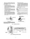
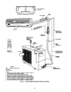
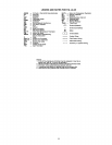
To access the LED indicator light, remove the front cover
of the unit by removing the 3 screws holding it in place.
If the LED indicator light continuously flashes on for one
second, then off for one second, the control is functioning
properly and no fault is present. A fast flashing LED indi-
cates that a fault has been detected. Table 10 lists the num-
ber of quick flashes and the associated fault. If the system
does not operate and the LED indicator does not flash, either
the power is offto the control board or the control board has
failed.
System Tests -- System tests listed below are per-
formed continuously by the microprocesson If a fault is
indicated, then the system allows only limited operation an-
til the problem is resolved. If the problem resolves itself,
then the code is cleared and operation resttmes.
THERMISTOR TESTS -- Each thermistor is testad for high
limit out of range (shorted condition) and low limit out of
range (open condition). If the thermistor is out of range, the
fault status indicator comes on and the LED flashes the ap-
propriate fault code. Proper thermistor location and correct
temperature sensing are critical to unit operation. Good ther-
mal contact is also required. Thermistor cable assemblies are
provided with fan coil units to run between indoor and out-
door units. High-voltage and thermistor cable assemblies should
not touch each other, and cable runs may be extended up to
200 feet.
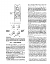
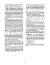
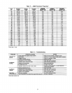
With unit running, the thermistor integrity may be checked
by measuring the dc voltage across the two thermistor con-
nections. Approximate temperature is indicated in Table 11.
COMPRESSOR FAILURE
lf the System is in Cooling or Dehumidification Mode-- Af-
ter 5 minutes of operation, if the temperature of the indoor
coil is not 4° F less than at the time the call for cooling started,
then a compressor failure is indicated on the remote con-
troller LCD display.
lf the System is in Heat Pump Heating Mode (38BK only) --
After 5 minutes of opemtinn, if the tempemture indicated by
the outdoor coil thermistor is not 4° F less than at the time
the call for heating started, then a compressor failure is
indicated.
REVERSING VALVE FAILURE (38BK Only)
If the System is in Cooling or Dehumidification Mode-- Af-
ter 5 minutes of operation, if the temperature at the indoor
coil is 4° F more than at the time the call for cooling started,
then a reversing valve failure is indicated.
If the System is in Heat Pump Heating Mode --After 5 min-
utes of operation, if the temperature indicated by the out-
door coil is 4° F more than at the time the call for heating
started, then a reversing valve failure is indicated.
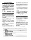
Table 10 --System Fault Codes
NO. OF QUICK
LED FLASHES SYSTEM FAULT
2 Room Air Thermistor
3 IndoorCoil Thermistor
4 Outdoor Coil Thermistor*
5 Compressor Malfunction
6 Reversing Valve Malfunction*
7 OutdoorAir Thermistor*
8 Indoor Fan Failure
9 Discharge AirThermistor
LEGEND
LED -- Light-EmittingDiode
*Heat pumpsystems only,
NOTE: Ifthe LED light continuously flashes onfor one second, then
off for one second, the control is functioning propedy and no fault is
present.
System Safeties and Interlocks
INDOOR FAN FAILURE -- If the indoor fan rpm shows
greater than 800 rpm for 30 seconds with the fan in the off
mode, then this test indicates an indoor fan failure. Also, if
the indoor fan rpm is greater than 1700 rpm for 30 seconds,
then this test indicates an indoor fan failure.
COMPRESSOR SHORT-CYCLING PROTECTION -- There
is a time delay of 3 minutes between compressor turning off
and turning back on.
INDOOR COIL FREEZE PROTECTION (Cooling or De-
humidification Mode Only) -- If the indoor coil tempera-
ture is less than or equal to 32 F for 10 minutes after the
compressor has started, then the compressor and outdoor fan
are turned off. The indoor fan continues to run at the user-
selected speed until the indoor coil reaches 44 F. At that time,
the compressor and outdoor fan will restart.
INDOOR COIL HIGH-TEMPERATURE PROTECTION
(Heat Pump Systems Only) If indoor coil temperature is
greater than or equal to 135 F, the outdoor fan shuts down.
The outdoor fan will restart automatically when the indoor
coil temperature drops to 120 F.
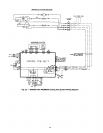
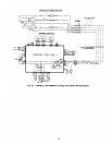
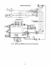
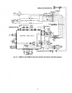
TROUBLESHOOTING
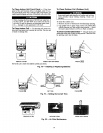
See Table 12 and Fig. 21-25 to assist in troubleshooting.
20