


7
Connect the Power Transformer —
An individual,
field-supplied, 24 vac power transformer is recommended for
each zone controller. If multiple zone controllers are powered
from one power transformer (100 va maximum for UL [Under-
writers’ Laboratories] Class 2 conformance), maintain polarity
on the power input terminals. All transformer secondaries are
required to be grounded. Use only stranded copper conductors
for all wiring to the zone controller. Wiring connections must
be made in accordance with NEC (National Electrical Code)
and local codes. Ground the transformer at the transformer lo-
cation. Provide an 18-gage, green, chassis ground wire at the
terminal.
The power supply is 24 vac ± 10% at 40 va (50/60 Hz).
For 33ZCVAVTRM zone controllers, the power require-
ment sizing allows for accessory water valves and for electric
heat contactor(s). Water valves are limited to 15 va on both
two-position and modulating hot water. The electric heat con-
tactor(s) are limited to 10 va (holding) each.
For 33ZCFANTRM zone controllers, the power require-
ment sizing allows for accessory water valves and for the fan
contactor. Water valves are limited to 8 va on both two-position
and modulating hot water. The fan contactor is limited to
11 va (holding).
NOTE: If a water valve or electric heat contactor exceeds
these limits, or external contactors are required for electric
heat, then it is recommended a 60 va transformer be used.
The maximum rating for any output is 20 va.
NOTE: Do not run sensor or communication wiring in the
same conduit with line-voltage wiring.
NOTE: An accessory conduit box (part no. 33ZCCONBOX) is
available for conduit wiring connections to the zone controller.
Perform the following steps to connect the power
transformer:
1. Install the field-supplied transformer in an electrical
enclosure that conforms to NEC and local codes.
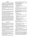
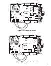
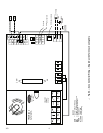
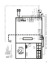
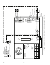
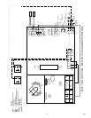
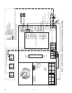
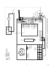
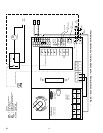
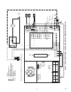
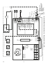
2. Connect 24 vac from the transformer as shown in the
applicable wiring diagram (Fig. 8A-J).
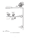
Connect Airflow Pickups —
The zone controller de-
termines velocity pressure by obtaining the difference between
high and low duct pressure from two airflow pickups. The
pickups are connected to barb fittings on the zone controller
with
1
/
4
-in. polyethylene tubing. All piping for this purpose
must conform to local codes.
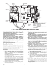
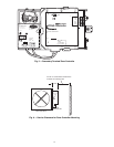
Figure 9 indicates the positions of the two barb fittings.
Perform the following steps to install and connect the air-
flow pickups:
1. Select a location on the air handler’s supply air duct
where the airflow pickups will be installed. The loca-
tion should be one where there are at least three duct
diameters of straight duct upstream of the pickups. If
this requirement is not met, stable airflow measure-
ments may not be possible.
2. Mount the field-supplied airflow pickup(s) in the duct,
following the manufacturer's directions. Two individ-
ual pickups may be used, one for high pressure airflow
and one for low pressure airflow. A dual pickup, which
combines the two functions, may also be used. When
using individual pickups, make sure that the one for
high pressure airflow faces upstream, in the direction
the air is coming from, and the one for low pressure
airflow faces downstream, in the direction the air is
going to.
3. Use field-supplied
1
/
4
-in. tubing (rated for the applica-
tion) to connect the high pressure airflow pickup to
barb fitting P1 on the pressure transducer. At the zone
controller, the P1 fitting is on the side with the filter
installed. Be careful to avoid sharp bends in the tubing,
because malfunctions may occur if the tubing is bent
too sharply. Use at least 2 ft of tubing for reading
stability.
4. Use field-supplied
1
/
4
-in. tubing (rated for the applica-
tion) to connect the low pressure airflow pickup to
barb fitting P2 on the pressure transducer. Be careful to
avoid sharp bends in the tubing, because malfunctions
may occur if the tubing is bent too sharply. Use at least
2 feet of tubing for stability.
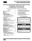
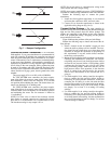
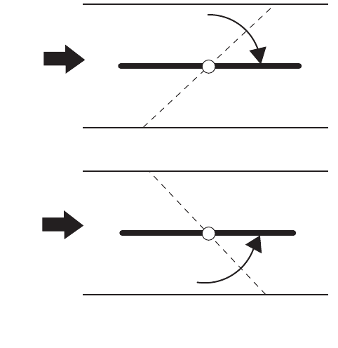
AIR
FLOW
AIR
FLOW
CW TO OPEN, CCW TO CLOSE
CCW TO OPEN, CW TO CLOSE
Fig. 7 — Damper Configuration