


34
LINKAGE COORDINATOR CONFIGURATION
SCREEN — The Linkage Coordinator Configuration screen
allows the user to set the linkage coordinator configuration set-
tings. See Table 6.
Linkage Master Zone
— This decision defines if the zone
controller will function as a Linkage Coordinator (Linkage
Master) for itself and other zones.
If the zone controller is to use a supply air sensor for stand-
alone operation, this configuration must be configured to No
and the number of Zones to 1.
If the zone controller will use its primary air sensor to deter-
mine the air handler mode for a number of zone controllers,
configure this configuration to Yes, input the number of zones,
and leave the air source decisions at the default values of zero.
If this zone controller will communicate linkage informa-
tion with an air source, configure this configuration to Yes. The
number of zones must be configured and the address of the air
source entered.
Linkage
Master Zone: Range Yes/No
Default Value No
Number of Zones
— This decision defines the number of zone
controllers (including itself) for the Linkage Coordinator to
scan and include as part of the average temperature, set points,
and occupancy information to the air source. The address of the
zone controller functioning as a Linkage Coordinator must be
larger than the number of zones configured. The zone control-
ler will scan addresses less than its own, including information
for as many zones as are configured. Other zone controller con-
figured as linkage coordinators will also be included, so it is
possible to have zones scanned by more than one linkage coor-
dinator. Therefore care must be taken in addressing to prevent
overlapping systems, unless overlapping systems is necessary.
In large buildings the use of bridges and multiple busses is rec-
ommended to improve communication and provide system
differentiation.
Number of
Zones: Range 1 to 128
Default Value 1
Air Source Bus and Element Number
— The Air Source Bus
and Element Number configurations define the address of the
air source providing conditioned air to the zones controlled by
the linkage coordinator. If the address is left at zero, the Link-
age coordinator will look for a primary air sensor to determine
the equipment mode. If no primary air sensor is installed, or the
sensor fails, the Linkage Coordinator will default the air source
mode to Cooling.
Air Source
Bus Number: Range 0 to 240
Default Value 0
Air Source
Element Number: 0 to 240
Default Value 0
Static Pressure Reset
— Air systems designed with diversity
(airflow required with all zones at maximum cfm exceeds de-
sign capacity of air handler) are capable of providing enough
CFM to all zones on days when conditions meet the demand at
design static. At other times, the air system does not require the
design static to meet the load requirements.
Static pressure reset allows the static pressure set point on
the air source to be reset whenever the system load is reduced
from the design maximum. The zone controller will then moni-
tor damper positions. When the system dampers are modulat-
ing at lower damper positions due to the higher static, the static
pressure will then be reset to a lower value allowing the damp-
ers to open more. This allows the system to automatically make
adjustments to the static pressure and optimize performance of
the fan which will reduce energy consumption.
The linkage coordinator monitors the position of all damp-
ers in its system. When any zone’s maximum damper position
reaches the Reset Maximum Damper Position, the linkage co-
ordinator will reduce the value of the reset variable.
The Maximum Damper Position and Static Pressure Reset
values can be viewed on the Linkage maintenance screen.
NOTE: The static pressure set point configured in the air
source should be the desired maximum (zero reset) static
pressure.
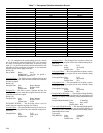
→
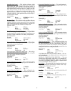
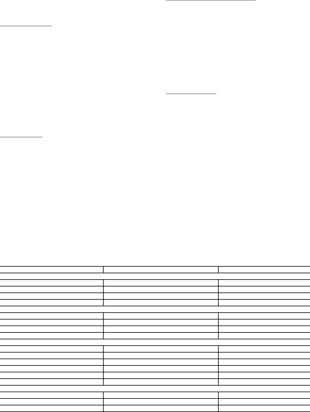
Table 6 — Linkage Coordinator Configuration Screen
DESCRIPTION DEFAULT POINT NAME
Zone Linkage
Linkage Master Zone
No MZENA
Number of Zones
1 NSYSTZ
Air Source Bus Number
0 ASBUSN
Air Source Element Number
0 ASELEMN
Static Pressure Reset
Reset Minimum Damper Position
50 % MINDP
Reset Maximum Damper Position
80 % MAXDP
Maximum Reset
0.0 in. wg SPMAX
SP Reset Variable Name
(blank) SPRVAR
CCN Linkage Data
CCN Variable Name
(blank) CCNVAR
CCN Function Configuration
3 CCNFUNC
Data Transfer Rate
10 minutes DATARATE
CCN Output Point
(blank) CCNOUTP
Destination Bus Number
0DESTBUSN
Destination Element Number
0DESTELEN
Temperature Sensor Grouping
Temperature Sensor Mode
1 BRD_RECV
Temperature Sensor Configuration
1SENSCFG
Broadcast Device ID
1 BRDDEVID
801