


39
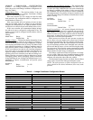
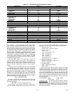
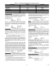
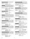
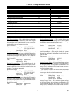
Table 10 — Terminal Service Configuration Screen
Probe Multiplier — This configuration is used to input a factor
for the velocity pressure probe installed in the terminal inlet.
Most inlet probes will have some aerodynamic characteristics
that will affect the differential pressure output from the probe.
The formula used by the ComfortID™ controller for calculat-
ing the airflow (cfm) is based on measuring velocity with a
Pitot tube probe. A PMF (Pitot measurement factor) is required
in the calculation for different probes. Because various probe
characteristics are different, the PMF is used to determine the
correct airflow based on the type of probe installed. The PMF
will compensate for the difference between Pitot-type probes
and the actual probe installed.
The default PMF value of 2.273 is the correct value to use
when the zone controller is used with a Carrier probe in a
Carrier air terminal. For terminals and probes supplied by other
manufacturers, the PMF must be calculated and entered into
the zone controller configuration in order to correctly measure
airflow.
To determine the correct PMF value, there are several meth-
ods depending on the data supplied by the terminal manufac-
turer. The manufacturer may supply a “K factor” or may sup-
ply a chart of velocity pressure vs. airflow for the terminal. The
K factor is the actual airflow velocity at a velocity pressure
reading of 1 in. wg for the probe. This value is in ft/min and
can be used to calculate the PMF. When the K factor is entered
into the following equation, it is compared to the value of 4005,
which is the K factor for a Pitot tube probe:
PMF = (4005/K FACTOR)
2
If a chart is supplied by the manufacturer instead of the K
factor, then the K factor can be calculated from the chart using
the following formula:
K FACTOR = (cfm at 1-in. wg)/(duct area ft
2
)
As an example, an air terminal with an 8-in. round inlet is
used. The terminal manufacturer has provided an airflow chart
that gives an airflow value of 820 cfm at a velocity pressure
reading of 1 in. wg. To determine the PMF for the terminal:
1. Determine duct area.
radius of duct = diameter of duct/2
radius = 8-in./2-in.
radius = 4-in.
Area of circular duct = Πr
2
Area = 3.14159 x 4
2
Area = 3.14159 x 16
Area = 50.26-in.
2
Area must be in ft
2
50.26-in.
2
/(144-ft
2
) = 0.34906 ft
2
2. Determine K factor.
K factor = (820 cfm/0.34906 ft
2
)
K factor = 2349 fpm
3. Determine PMF.
PMF = (4005 fpm/2349 fpm)
2
PMF = 2.907
Another way to determine the probe constant for a probe
without documentation is to measure the velocity pressure with
a Magnahelic gage. Open the damper and adjust the static pres-
sure or open the damper until you have one inch of velocity
pressure on the Magnahelic gage. Measure the total CFM of air
being delivered. The CFM just measured divided by the inlet
area in square feet should equal the K factor for the formula.
Now use the K factor that was empirically derived to determine
the probe multiplier.
Probe Multiplier: Range 0.250 to 9.999
Default Value 2.443
Calibration Gain
— Air terminal testing by industry standards
is done with straight duct, upstream of the terminal. Since some
applications do not get installed in this manner, the actual air-
flow from the terminal at balancing may not equal the reading
from the zone controller.
DESCRIPTION DEFAULT POINT NAME
COOLING
Terminal Type
1 TERMTYPE
Primary Inlet Size
Inlet Diameter
Inlet Area
6.0 in.
0.0 in.
RNDSZ
SQA
Probe Multiplier
2.443 PMF
Calibration Gain
1.000 CAL_GAIN
Offset
0 cfm OFFSET
Damper
Proportional Gain
Integral Gain
Derivative Gain
Starting Value
30.0
5.0
0.0
20 %
KP
KI
KD
STARTVAL
CW Rotation
Close DMPDIR
Pressure Independent
Ye s P R ESI ND
HEATING
Heat Type
0 HEATTYPE
VAV Central Heating
Ye s C ENHEAT
Heating
Proportional Gain
Integral Gain
Derivative Gain
Starting Value
8.0
3.0
0.0
80 F
KP
KI
KD
STARTVAL
Ducted Heat
Yes DUCTHEAT
Maximum Temperature
110 F MAXTEMP
Number of Electric Heat Stages
1STAGES
Heat On Delay
2HONDEL
Fan Off Delay
2 FNOFFD
2-Position Heat Logic
Normal HEATYPE
SPT Trim
0.0 F SPTTRIM
SAT Trim
0.0 F SATTRIM
Remote Contact Configuration
Close RMTCFG
303
→