


32
SUPPLY AIR TEMPERATURE — Temperature of the air
leaving the zone controller downstream of any ducted heat
source. Measured by a 10 kΩ thermistor (Type III). This tem-
perature is used to control the maximum discharge air to the
space when local heat is active. The sensor is not required or
recommended for cooling only terminals. If supply air temper-
ature display is required by specification, on a cooling only
box, a heat type other than zero must be configured. This
will have no adverse affect on the operation of a cooling only
terminal.
Supply
Air Temperature: Display Units F (C)
Default Value 0.0
Display Range -40.0 to 245.0
Network Access Read/Write
LOCAL HEATING CAPACITY — When local heat at the
terminal is enabled the percent of heat being delivered is deter-
mined by the following formula for modulating (floating point)
type heat:
% Capacity = [(SAT - SPT)/(Maximum Duct Temp – SPT )]
The percent of heat delivered is determined by the follow-
ing for two-position hot water or staged electric heat:
% Output Capacity = (# of active stages/Total stages) * 100
Local Heating
Capacity: Display Units % output capacity
Default Value 0
Display range 0 to 100
Network Access Read only
TERMINAL FAN — The commanded output for the terminal
fan on a fan powered terminal.
Terminal Fan: Display Units Discrete ASCII
Default Value Off
Display Range Off/On
Network Access Read/Write
RELATIVE HUMIDITY — Space Relative Humidity read-
ing from the optional relative humidity sensor. Used by Hu-
midity control function if configured.
Relative
Humidity: Display Units % RH
Default Value 0
Display Range 0 to 100
Network Access Read/Write
AIR QUALITY — Indoor air quality reading from a CO
2
sen-
sor installed in the space. Used by Air Quality control function
if configured.
Air Quality (ppm):Display units None shown (parts per
million implied)
Default Value 0
Display range 0 to 5000
Network Access Read/Write
SECONDARY AIRFLOW — Airflow reading from the sec-
ondary pressure transducer, supplied with the secondary actua-
tor, intended for dual duct and pressure control applications.
Secondary
Airflow: Display Units cfm
Default Value 0
Display Range 0 to 9999
Network Access Read/Write
PRIMARY AIR TEMPERATURE — Primary air tempera-
ture from sensor (10 kΩ, Type III), located in main trunk of
ductwork for supply air provided by the air-handling equip-
ment. Used for linkage coordination.
Primary Air
Temperature: Display Units F (C)
Default Value 0.0
Display Range -40.0 to 245.0
Network Access Read/Write
HEAT ENABLE/DISABLE — Provides enable/disable
function for local heat at the terminal. When enabled the Local
heat capacity function will run to operate the terminal heat.
Heat Display: Display Units Discrete ASCII
Default Value Dsable
Display Range Dsabe/Enable
Network Access Read/Write
Modify Controller Configuration —
In Service
Tool software, select the desired zone controller and access the
Modify Controller Configuration Menu screen. This configura-
tion screen is also displayed under CONFIGURE when using
ComfortWORKS
®
and ComfortVIEW™ software.
The Modify Controller Configuration Menu screen is used
to access the Alarm Limit Configuration screen, Controller
Identification screen, Holiday Configuration screen, Linkage
Coordinator Configuration screen, Occupancy Configuration
screen, and Set Point screen.
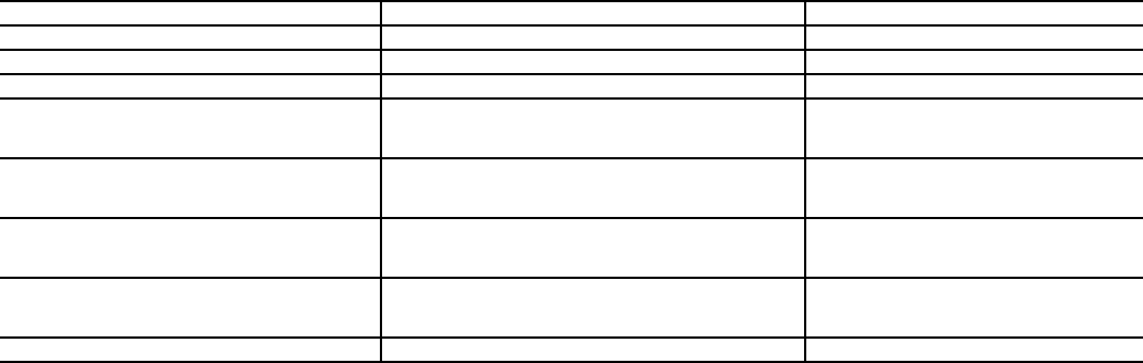
ALARM LIMIT CONFIGURATION SCREEN — The
Alarm Limit Configuration screen is used to configure the
alarm settings for the zone controller. See Table 5.
→
Table 5 — Alarm Limit Configuration Screen
DESCRIPTION DEFAULT POINT NAME
Alarm Routing Control
00000000 ROUTING
Re-Alarm Time
0RETIME
SPT Occupied Hysteresis
5.0 F SPTHYS
Unoccupied SPT
Low Limit
High Limit
40 F
99 F
LOWLIM
HIGHLIM
Occupied RH
Low Limit
High Limit
10 %
99 %
LOWLIM
HIGHLIM
Unoccupied RH
Low Limit
High Limit
0 %
100 %
LOWLIM
HIGHLIM
Air Quality
Low Limit
High limit
250 ppm
1200 ppm
LOWLIM
HIGHLIM
High Velocity Pressure
1.2 in. wg HIGHVP
801