


23
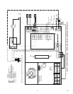
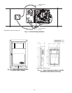
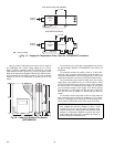
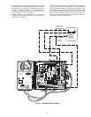
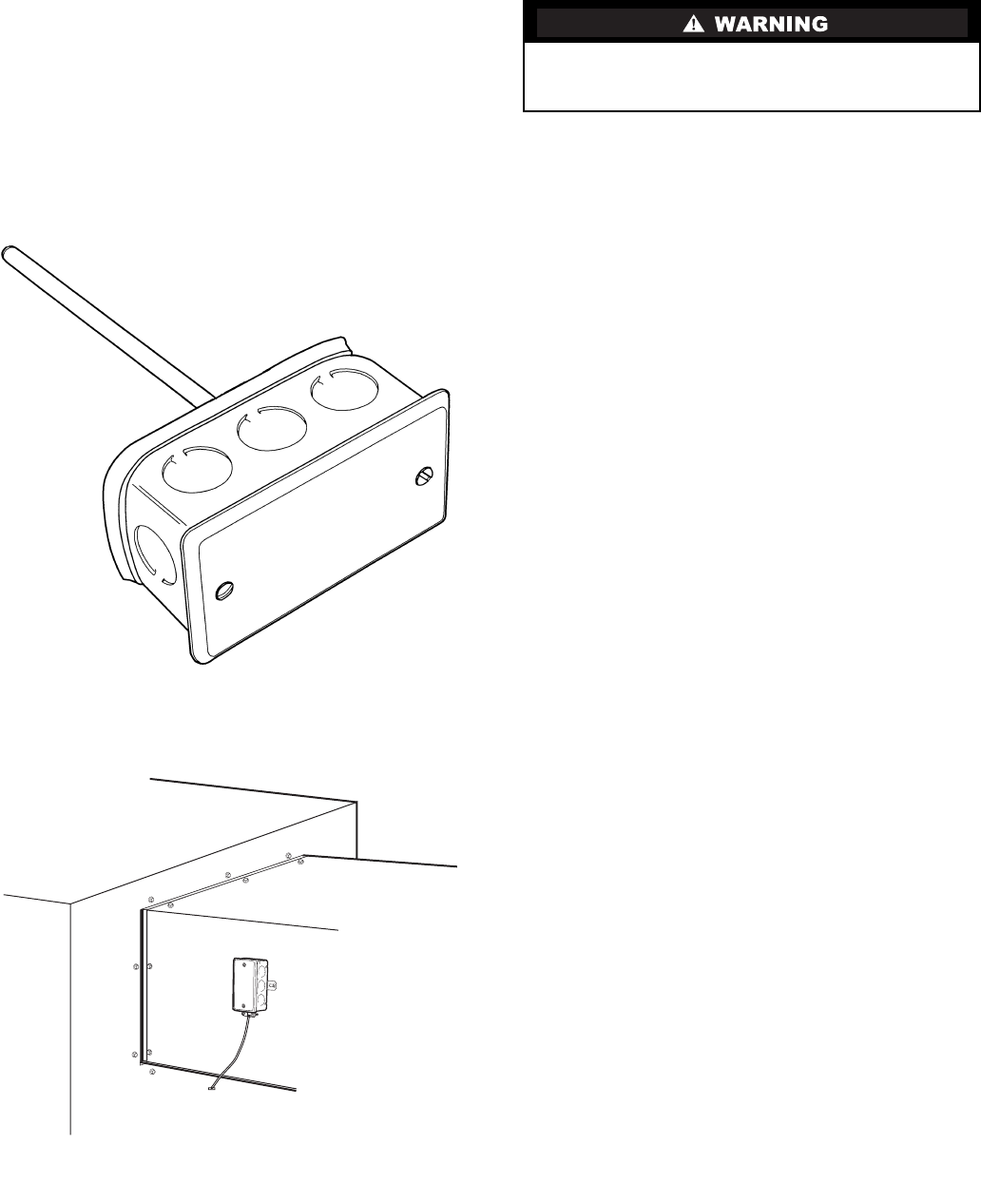
PRIMARY AIR TEMPERATURE SENSOR INSTALLA-
TION — A primary air temperature (PAT) sensor is used on a
zone controller which is functioning as a Linkage Coordinator
for a non CCN/Linkage compatible air source. The part num-
ber is 33ZCSENPAT. See Fig. 15.
When used on a zone controller, try to select a zone control-
ler which will allow installation of the PAT sensor in the main
trunk, as close to the air source as possible. See Fig. 16.
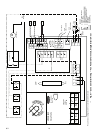
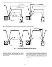
SUPPLY AIR TEMPERATURE (SAT) SENSOR INSTAL-
LATION — On terminals with heat, the SAT sensor is re-
quired. The SAT must be installed in the duct downstream
from the air terminal. The SAT sensor is also sometimes called
a duct temperature (DT) sensor. The part number is
33ZCSENSAT.
The SAT sensor probe is 6 inches in length. The tip of the
probe must not touch the inside of the duct. Use field-supplied
bushings as spacers when mounting the probe in a duct that is
6 in. or less in diameter.
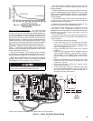
If the unit is a cooling only unit, the SAT is not required.
If the unit is equipped with electric reheat, ensure that the
sensor is installed at least 2 ft downstream of the electric heater.
See Fig. 17 for the sensor location in this application.
If the unit has an octopus connected directly at the dis-
charge, install the sensor in the octopus. If the unit has an elec-
tric heater, the two foot minimum distance between the sensor
and the heater must be maintained. See Fig. 17 for the sensor
location in this application.
Do not run sensor or relay wires in the same conduit or race-
way with Class 1 AC or DC service wiring. Do not abrade, cut,
or nick the outer jacket of the cable. Do not pull or draw cable
with a force that may harm the physical or electrical properties.
Avoid splices in any control wiring.
Perform the following steps to connect the SAT sensor to
the zone controller:
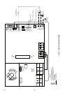
1. Locate the opening in the control box. Pass the sensor
probe through the hole.
2. Drill or punch a
1
/
4
-in. hole in the duct downstream of
the unit, at a location that conforms to the require-
ments shown in Fig. 17.
3. Use two field-supplied, self-drilling screws to secure
the sensor probe to the duct. Use field-supplied bush-
ings as spacers when installing the sensor probe in a
duct 6 in. or less in diameter.
Perform the following steps if state or local code requires
the use of conduit, or if your installation requires a cable length
of more than 8 ft:
1. Remove the center knockout from a field-supplied 4 x
2-in. junction box and secure the junction box to the
duct at the location selected for the sensor probe.
2. Drill a
1
/
2
-in. hole in the duct through the opening in
the junction box.
3. Connect a
1
/
2
-in. nominal field-supplied conduit
between the zone controller enclosure and the junction
box.
4. Pass the sensor probe wires through the conduit and
insert the probe in the duct. Use field-supplied bush-
ings as spacers when installing the sensor probe in a
duct 6 in. or less in diameter.
5. Secure the probe to the duct with two field-supplied
self-drilling screws.
6. If you are extending cable length beyond 8 ft, use ple-
num rated, 20 AWG, twisted pair wire.
7. Connect the sensor leads to the zone controller’s wir-
ing harness terminal board at the terminals labeled
SAT and GND.
8. Neatly bundle and secure excess wire.
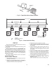
INDOOR AIR QUALITY SENSOR INSTALLATION —
The indoor air quality (IAQ) sensor accessory monitors carbon
dioxide levels. This information is used to modify the position
of the outdoor air dampers to admit more outdoor air as
required to provide the desired ventilation rate. Two types of
sensors are supplied. The wall sensor can be used to monitor
the conditioned air space; the duct sensor monitors the return
air duct. Both wall and duct sensors use infrared technology to
measure the levels of CO
2
present in the air. The wall sensor is
available with or without an LCD readout to display the CO
2
level in ppm. See Fig. 18.
The sensor part number is 33ZCSENCO2. To mount the
sensor, refer to the installation instructions shipped with the ac-
cessory kit.
Disconnect electrical power before wiring the zone control-
ler. Electrical shock, personal injury, or damage to the zone
controller can result.
Fig. 15 — Primary Air Temperature Sensor
(Part Number 33ZCSENPAT)
Fig. 16 — Primary Air Temperature Sensor
Installation (Unit Discharge Location)
→
800