


38
Heat Minimum (PI)
— This configuration is the minimum
airflow the terminal will control to when the equipment mode
is Warm-Up or Heat. If the terminal is not configured for VAV
central heating this is the only airflow the terminal will control
to for these equipment modes.
Heat Minimum: Units CFM
Range 0 to 9999 (Limited by
the High Velocity pressure limit alarm)
Default Value 0
Heat Maximum (PI)
— This configuration is used to config-
ure the maximum airflow at which the zone controller will op-
erate if VAV central heat is configured to yes. If the equipment
mode is heat or warm-up, and the demand in the space is for
heat, the zone controller will calculate the proper airflow need-
ed to achieve space temperature set point (operating between
the Heat Min and Heat Max).
Heat Maximum: Units CFM
Range 0 to 9999 (Limited by
the High Velocity pressure limit alarm)
Default Value 4000
Parallel Fan On (PI)
— This configuration is used to define
the primary airflow setting below which a parallel fan terminal
should energize its fan. The setting should be used to allow a
low volume of primary airflow to be better diffused into the
space.
Parallel Fan On: Units CFM
Range 0 to 9999 (Limited by
the High Velocity pressure limit alarm)
Default Value 0
Dual Duct CV Airflow (PI)
— This configuration defines the
Dual Duct, constant volume, total airflow set point.
Dual Duct
Airflow: Units CFM
Range 0 to 9999 (Limited by
the High Velocity pressure limit alarm)
Default Value 4000
Pressure Dependent
— Pressure Dependent (PD) set points
should be configured for backup pressure dependent operation,
if an operating problem with the pressure transducer occurs.
Cool Minimum Position (PD)
— This configuration is the
minimum damper position the terminal will control to when
the equipment mode is Cooling (or Fan Only), or free cooling
and the space requirements for cooling are at a minimum.
Cool Minimum
Position: Units %
Range 0 to 100
Default Value 0
Cool Maximum Position (PD)
— This configuration is the
maximum damper position the terminal will control to when
the equipment mode is cooling (or fan only), or free cooling
and the space requirements for cooling are at a maximum.
Cool Maximum
Position: Units %
Range 0 to 100
Default Value 100
Reheat Minimum Position (PD)
— This configuration is for
single duct units with ducted reheat. Configure the desired
damper position at which the reheat will provide optimum per-
formance. This value is compared to the Minimum Cool value
and the greater of the two values is used to determine the
damper position.
Reheat Minimum
Position: Units %
Range 0 to 100
Default Value 0
Heat Minimum Position (PD)
— This configuration is the
Minimum damper position the terminal will control to when
the equipment mode is Warm-Up or Heat. If the terminal is not
configured for VAV central heating this is the only position the
terminal will control to for these equipment modes.
Heat Minimum
Position: Units %
Range 0 to 100
Default Value 0
Heat Maximum Position (PD)
— This configuration is used
to configure the maximum damper position at which the zone
controller will operate if VAV central heat is configured to yes.
If the equipment mode is Heat or Warm-Up and the demand in
the space is for heat the zone controller will calculate the prop-
er damper position needed to achieve space temperature set
point, operating between the Heat Min and Heat Max.
Heat Maximum
Position: Units %
Range 0 to 100
Default Value 100
Deadband Percent
— This configuration is used to configure
the Deadband Percent that the airflow will operate with.
Deadband
Percent: Units %
Range 0.0 to 100.0
Default Value 12.5
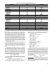
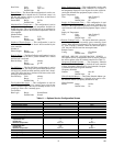
TERMINAL SERVICE CONFIGURATION SCREEN —
The Terminal Service Configuration screen lists the main con-
figuration settings for the air terminal controller. See Table 10.
Terminal Type
— This configuration is used to indicate the
terminal type that the zone controller is installed on. A 1 is for
Single Duct terminals, a 2 is for Parallel Fan terminals, a 3 is
for Series Fan terminals, and a 4 is for Dual Duct applications.
Terminal Type: Range 1 to 4
Default Value 1
Primary Inlet Size
— The Primary Inlet Size configuration is
used to input the inlet diameter of the terminal if used with a
round inlet. The Inlet Area configuration is used for oval or
rectangular inlets. The zone controller will use the larger value
for CFM calculations if both values are configured.
NOTE: Carrier sizes 12, 14, and 16 are oval.
Primary Inlet Size
(Inlet Diameter): Units Inches
Range 3.0 to 24.0
Default Value 6.0
Inlet Area — The Inlet Area configuration is used if the termi-
nal has an oval or rectangular inlet. The Primary Inlet Size
configuration is used for round inlets. The zone controller will
use the larger value for CFM calculations if both values are
configured.
Inlet Area: Units Square Inches
Range 0.0 to 500.0
Default Value 0.0
IMPORTANT: Pressure dependent settings are
included for use only in the event of a pressure trans-
ducer failure. The inclusion of these configuration set-
tings does not indicate that Carrier is endorsing this
product for pressure dependent operation. In the case
of a pressure sensor failure, the zone controller will
broadcast a pressure sensor failure message on the
CCN bus. These configurations may be used by a ser-
vice technician to put the terminal in pressure depen-
dent mode until the zone controller can be replaced.