


8
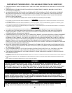
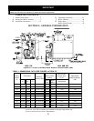
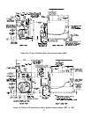
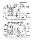
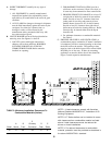
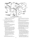
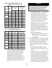
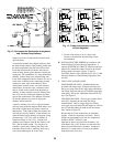
Figure 4: Boiler Tapping Locations and Usage (Knockdown Boilers Only)
PURPOSE OF TAPPINGS
Tappin
g
Location
Size
Steam Boiler Water Boiler
Non-Heater w/Heater Non-Heater Front Heater Rear Heater
A¾"
PA404A Pressuretrol (Probe LWCO)
Plugged (Float LWCO)
L8148A
Operating Control
L8124C
Operating Control
Flush Plug
B ¼" Pressure/Vacuum Gauge Temperature/Pressure Gauge
C¾"
Probe LWCO Std.
Plugged (Float LWCO)
Flush Plug
C-C ¾" Flush Plug Flush Plug Flush Plug
D½"
Water Gauge Glass (Probe LWCO)
Water Gauge Glass, Pressuretrol, and LWCO (Float)
Flush Plug
F ¾" -----
L4006A Operating
Control
----- Disregard
L8124C
Operating Control
G 1½" Bushed to ¾" for Draincock (Optional Return) Return
H 1½" Return Bushed to ¾" for Draincock (Optional Return)
J 1½" Surface Blowoff - Plugged Flush Plug
K 2" Front Supply (3 thru 9 Section) Front Supply (3 thru 9 Section)
L2"
Plugged, Optional Second Supply (3 thru 5 Section)
Required Second Supply (6 thru 9 Section)
Plugged (3 thru 9 Section)
M ¾" Safety Valve Relief Valve
P ¾" Auxiliary Tapping - Plugged
Aux. Tapping -
Plugged
Disregard
Aux. Tapping -
Plugged
R ¾" Auxiliary Tapping - Plugged Auxiliary Tapping - Plugged