


22
F. REMOVE GUN ASSEMBLY
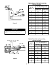
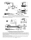
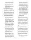
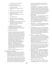
1. Items to be checked are nozzle size, type, and
angle; head size (and setting on MD(V1)head); gun
setting; and positioning of electrodes. This
informations is shown in Figures 23 and 24 and
Table 6 (at rear of manual).
2. Reinstall gun assembly.
G. ADJUST OIL BURNER BEFORE STARTING.
1. SET BURNER AIR BAND AND AIR SHUTTER,
see Table 6 at rear of manual..
2. OPEN ALL OIL LINE VALVES.
3. Attach a plastic hose to fuel pump vent fitting and
provide a pan to catch the oil.
4. REMOVE GAUGE PORT PLUG from fuel pump
and install pressure gauge capable of reading at
least 150 PSI.
5. OPEN FLAME OBSERVATION DOOR on front
of boiler.
H. START OIL BURNER.
1. Open vent fitting on fuel pump.
2. TURN ‘ON’ BURNER service switch and allow
burner to run until oil flows from vent fitting in a
SOLID stream without air bubbles for
approximately 10 seconds.
3. Close vent fitting and burner flame should start
immediately.
I. ADJUST OIL PRESSURE.
1. Locate oil pressure adjusting screw and turn screw
to obtain 140 PSI pressure (100 PSI for V74R
only).
2. DO NOT REMOVE PRESSURE GAUGE until
later.
J. OTHER ADJUSTMENTS
1. ADJUST THE AIR BAND AND/OR AIR
SHUTTER.
Adjust air supply by loosening lock screws and
moving the air shutter and if necessary the air band.
Refer to Table 6 for preliminary settings.
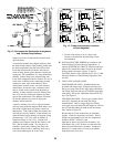
2. ADJUST THE COMBUSTION HEAD.
V72 thru V77; V713 and V714:
"L1" and "F" head burners have a fixed head which
is non-adjustable. To check combustion head
location refer to Figure 24.
V78 & V79:
“V1” (variable) head burners have the ability to
control air by moving the head either forward or
back.
Loosen the adjusting plate assembly hold down
screw. Slide the head and plate to the required
firing rate setting as shown in Figure 24. Tighten
the screw and knurled nut.
It might be necessary to move the head forward or
back one position at a time to optimize the smoke
and CO
2
readings. See Figure 24.
3. ADJUST DRAFT REGULATOR for a draft
of — .02” (water gauge) over the fire after chimney
has reached operating temperature and while
burner is running.
4. READJUST AIR BANDS on burner for a light
orange colored flame while the draft over the fire is
—.02”. Use a smoke tester and adjust air for
minimum smoke (not to exceed #1) with a
minimum of excess air. Make final check using
suitable instrumentation to obtain a CO
2
of 11.5 to
12.5% with draft of —.02” (water gauge) in fire
box. These settings will assure a safe and efficient
operating condition. If the flame appears stringy
instead of a solid fire, try another nozzle of the
same type. Flame should be solid and compact.
After all adjustments are made recheck for a draft
of —.02” over the fire.
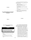
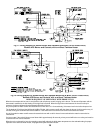
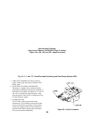
Fig. 23: "F" Head Electrode Positioning and Gun
Setting (Beckett AFG)
(Non-Burnham Drawing
Copy from other Manual)
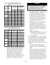
NOTICE
Burner-specific references in the following instructions pertain to the Beckett AFG, supplied as
standard equipment. For optional burners, Riello R40 and Carlin EZ-1HP and 102CRD-3, consult
Table 6 at the rear of this manual for specifications, the instruction booklet shipped with the
burner, and the appropriate Supplemental Instructions shipped with the boiler:
Supplemental Instructions for: Riello R40
Carlin EZ-1HP
Carlin 102CRD-3
Burnham Part Number
8142761
8142759
8142760