


7
SECTION II: KNOCKDOWN BOILER ASSEMBLY
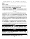
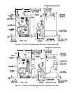
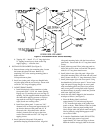
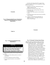
A. REMOVAL OF BARE BOILER FROM SKID
1. Boiler is secured to base with 4 bolts, 2 on front and
2 on rear, see Figure 2. Remove all bolts.
2. Tilt boiler to right and to rear. Using right rear leg
as pivot, rotate boiler 90° in a clockwise direction,
and lower left side of boiler to floor. Tilt boiler and
remove crate skid.
Note: If Boiler is Packaged Go To Section III
Figure 2
B. MOVE BOILER TO PERMANENT POSITION by
sliding or walking.
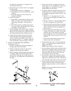
C. TEST BOILER FOR LEAKS before installing
controls, trim, and jacket, and before connecting to
heating system.
1. Loosen nuts on tie rods until only finger tight.
2. Install pressure gauge (at least 30 P.S.I. capacity), a
hose to the city water and a valve in the supply
tapping. Plug remainder of tappings.
3. Fill boiler with water and apply a pressure of at
least 10 pounds but no more than 30 pounds gauge
pressure.
4. Examine Boiler carefully inside and outside for
leaks or damage due to shipment or handling.
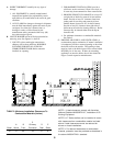
D. DRAIN WATER FROM BOILER. Remove gauge,
valve and plugs from those tappings to be used. Leave
other tappings plugged or bushed according to Figure
4.
E. INSPECT JOINTS BETWEEN SECTIONS. All joints
are factory sealed. If there are any spaces due to
shipment or handling, seal them with boiler putty.
F. INSPECT FLUE COVER PLATES for tightness. If
loose, retighten mounting hardware. If flue plate or
sealing insulation is damaged repair or replace as
needed.
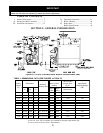
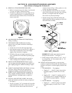
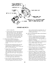
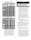
G. INSTALL AND SECURE CANOPY with cerafelt
gasket and hardware provided to ensure gas tight seal
— see Figure 3.
1. Cut two (2) strips 13 ¾” lg. from the roll of cerafelt
gasket insulation. Place one (1) strip across the top
of the front section and the other across the rear
section as shown in Fig. 3. Place gaskets so as not
to allow any flueway blockage.
2. Cut the remainder of the roll into two (2) equal
pieces. Place each piece along the sides, allowing
the ends to overlap the front and rear pieces.
Do not allow any flueway blockage.
3. Position canopy body within the retaining bar
which borders the flueway openings on top of the
bare boiler block assembly.
IMPORTANT: Jacket support bracket must be
facing left side of boiler — see Figure 3.
4. Secure canopy to boiler with two (2) 1/4" - 20 x 3"
lg. carriage bolts, 1/4" flat washers and 1/4" - 20
wing nuts provided.
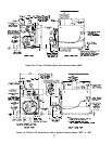
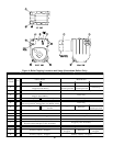
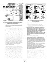
H. INSTALL the following steam or water trim that
would be concealed or inaccessible after flush jacket is
installed, see Figure 4 for boiler tapping locations and
usage.
1. STEAM BOILER — Top tappings:
a. Tapping "L" — Install 2" plug in rear section
top supply tapping on boiler sizes V73 thru
V75.
b. Tapping “M” — Install ¾” coupling and ¾” x
8” long nipple into ¾” tapping located next to
front section top supply tapping — all boiler
sizes.
2. WATER BOILER — Top tappings:
a. Tapping “L” — Install 2” plug in rear section
top supply tapping on boiler sizes V73 thru
V79.
Figure 3