


10
manner as rating label.
c. On steam boilers, install the Lowest Permissible
Water Level Plate, Form No. 1204 (shipped in
Steam Trim Carton), on the jacket right side
panel. Align the two holes in the plate with the
two 1/8” dia. holes located near the front edge,
in line with the lower sight glass tapping, and
secure with #8 x ½” lg. sheet metal screws.
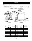
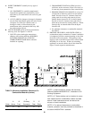
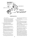
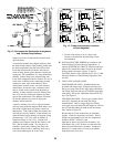
J. INSTALL OIL BURNER (See Figure 6).
1. Check target wall and cerafelt blanket in
combustion chamber. If any damage or movement
occurred during shipment, repair or replace as
needed.
2. Check the burner mounting plate and swing door
insulation pieces for damage and adhesion. If
damaged, replace insulation. If loose, re-attach with
RTV 732 or 736 silicone caulk.
3. Engage bottom slot on burner mounting plate with
matching bolt in bottom tapping of front section.
Align mounting holes and fasten the mounting
plate to the boiler sections with (5) five 5/16” bolts
and washers removed in step 8a. Fully tighten all
bolts.
4. Place burner flange gasket on burner swing door
and thread two 5/16” x ½” long bolts into vertical
set of holes approximately three full turns.
5. Insert oil burner air tube into the opening of the
burner swing door. Align keyhole slot with vertical
set of bolts, engage hex head of bolts and rotate
burner to the left. Install two remaining 5/16” x ½”
long bolts in horizontal sets of holes. Level burner
and fully tighten all bolts.
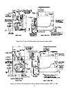
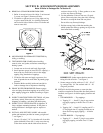
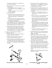
K. INSTALL STEAM BOILER TRIM AND CONTROLS
(See Figures 1C & 4).
1. Thread the combination pressure/vacuum gauge
into the ¼” tapping. Tighten with wrench applied
to the square shank of the gauge. Do not apply
pressure to the gauge case — this might destroy the
calibration of the gauge.
2. Thread 1½” x ¾” bushing and a ¾” drain cock into
the 1½” tapping located in the lower right corner of
the front casting. Tighten with wrench.
NOTE: Lower rear section tapping “H” is used for
standard condensate return on steam boilers.
3. Thread safety relief valve, as shown in Figure 1C,
into 3/4" coupling and 3/4” x 8” nipple previously
installed in step H. Tighten with wrench.
NOTE: Pipe discharge as shown in Figure 8.
4. Install probe type LWCO if so equipped. Thread
probe into ¾” tapping located on the front section
directly above the protectorelay on the oil burner.
Read the manufacturer’s instructions packed with
the probe LWCO for proper pipe dope application.
DO NOT use Teflon tape on probe threads. Use of
teflon can render the probe LWCO inoperational.
Slip the LWCO control over the probe and clamp in
place. Connect the wire(s) between the probe and
control per the manufacturer’s instructions. Install
Figure 6