


11
the sight glass using the two ½” tappings to the
right of the probe LWCO.
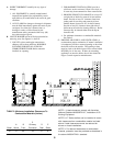
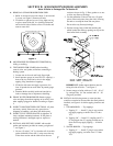
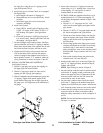
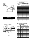
5. Install float-type Low Water Cutoff, if so equipped.
See Figure below.
a. Install nipples and unions in Tappings D.
b. Mount hardware to low water cutoff body. Install
assembly.
c. Install water gage glass on low water cutoff
assembly's tee fittings.
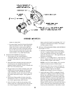
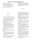
6. Install Limit Control.
a. Probe LWCO: Install Limit in Tapping A using
¾ NPT x 2" nipple, ¾ NPT elbow, ¾ NPT x ¼
NPT bushing, and syphon. See Figure below
right.
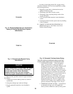
b. Float LWCO: Remove ¼ NPT plug from top of
Low Water Cutoff. Install Syphon and Limit into
this tapping. See Figure below.
7. On units equipped with a tankless heater, install the
aquastat controller well in the ¾” tapping in tankless
heater plate. Slip the bulb of the aquastat into the well
and secure the control in place with the set screw.
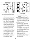
8. Connect the field wiring to the pressure limit, the
LWCO, the burner J-box, and from the aquastat
control (if equipped with tankless heater) to the oil
burner primary control's "T-T" terminals. Make the
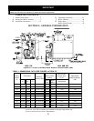
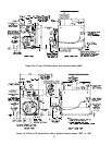
wiring connections as shown in Figures 17 thru 20.
L. INSTALL WATER TRIM AND CONTROLS
(See Figures 1B and 4).
1. Thread ½” pipe plugs into gauge glass tappings in
the upper right side of front section.
2. Thread ¾” pipe plug in probe low water cut off
tapping (just left of gauge glass tappings).
3. Thread combination pressure/temperature gauge into
¼” tapping. Tighten with wrench applied to the
square shank of the gauge. Do not apply pressure to
the gauge case - this might destroy the calibration of
the gauge.
4. Screw drain valve into 1½” tapping in lower rear
section using 1½” x ¾” bushing (note - lower front
section tapping “G” (see Figure 4) is used for
standard return on water boilers).
5. If CIRCULATOR (not supplied with boiler) is to be
mounted directly to 1½" boiler return tapping "G",
use the piping arrangements outlined in steps a. thru
e. as follows:
a. Thread 1½” x 3” long nipple and 1½” x 90°
elbow into the return tapping and tighten with a
pipe wrench.
b. Thread 1½” NPT x 15” long pipe nipple into the
90° elbow and tighten with a pipe wrench.
c. Thread one of the circulator flange onto the pipe
nipple and tighten with a pipe wrench. Position
flange so that the bolt slots are perpendicular to
the boiler front.
d. Place a flange gasket in the flange groove on the
circulator and mount the circulator on the flange
installed in step 3. Note that this is the return
piping and the flow arrow on the circulator should
point down ê. Fasten circulator with 7/16” nuts
and bolts.
e. Bolt second circulator flange and gasket to the
circulator with 7/16” nuts and bolts.
6. Install pressure relief valve, as shown in Figure 1B,
onto ¾” x 8” nipple previously installed in Step H.
Tighten with wrench.
NOTE: Pipe discharge as shown in Figure 9.
7. On units without a tankless heater, install the control
well into the ¾” tapping located on the front of the
boiler in the upper left corner. Tighten the well and
insert the control’s bulb into the well. Secure the
control with set screw on the control.
8. On units with a tankless heater, install the control
well in the ¾” tapping on the tankless heater plate.
Tighten the well and insert the control’s bulb into the
well. Secure the control with set screw on the control.
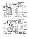
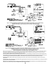
9. Connect the field wiring from the circulator to the
control and from the control to the burner J-Box.
Make the wiring connections as shown on Figures 21
and 22.
NOTE: Proceed to Installation Instructions Section
III, step E, to continue.
Float-type Low Water Cutoff Installation
Limit Installation for Probe LWCO Equipped
Boilers