


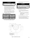

7
II. Unpack Boiler
CAUTION
Do not drop boiler. Do not bump boiler jacket
against oor.
A. REMOVE CRATE
1. Remove all fasteners at crate skid.
2. Lift outside container and remove all other inside
protective spacers and bracing. Remove vacuum
relief valve and miscellaneous trim bag containing
safety/relief valve, and pipe ttings.
B. REMOVAL OF BOILER FROM SKID
1. Boiler is secured to base with 2 bolts, 1 at left front
and 1 at right rear. Remove both bolts.
2. Tilt boiler, "walk" boiler backward, and set rear
legs down on oor. Tilt boiler backward, pull skid
forward and set front legs down on edge of skid.
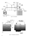
Install close nipple, tee, and plug in return coupling.
See Section III and Figure 5. Point tee toward
permanent return location.
3. Tilt boiler backward and remove skid. Be careful not
to damage Burner or Jacket.
C. DETERMINE PROPER HINGE LOCATION FOR
BURNER SWING DOOR. Boiler is shipped with
hinges on left side. Approximately 12 inches are
required on the hinge side for burner clearance. If there
will be less than 12 inches from left side of boiler to
wall, move hinges to right side (refer to Paragraph D).
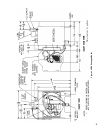
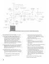
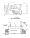
D. HINGE LOCATION CHANGE (if required) (refer to
Figure 3).
1. Pull 2 halves of Burner Swing Door Interlock apart.
Swing Door Interlock is connected to T-T terminals
on R7184P Control. Lift Honeywell R7184P Control
off of Burner Junction Box and disconnect wiring
harness from burner.
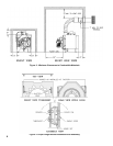
2. Remove 8 sheet metal screws from jacket. Remove
rear jacket box and bend both sides of Jacket
Wrapper up, see Figure 22.
3. Remove 2 (two) 5/16" - 18 x 3" long hex head cap
screws and at washers from right side of door.
Remove 2 hairpin cotter pins and 2 hinge pins
from hinges on left side of door and remove Door
Assembly from boiler. Inspect Front and Rear Door
Insulation Pieces and Combustion Chamber Liner,
see Paragraph G.
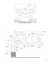
4. Remove 4 hex nuts from bolts that attach hinges and
hinge spacers to left side of Tubesheet. Remove 4
hex head cap screws that attach hinges to door.
5. Attach 2 hinge brackets & spacers to Tubesheet and
2 hinge brackets to Door on right side of boiler. 3
Holes in each Hinge Bracket must line up with 3
matching holes in Spacer, Tubesheet or Door. See
Figure 3. Tighten hex nuts, bolts and screws by
hand only.
6. Replace door assembly. Hinge brackets attached to
door must rest on top of hinge brackets attached to
tubesheet. See Figure 3. Slide hinge pins through
hinges from top and install cotter pins. Close door
and install 5/16" - 18 x 3" long hex head cap screws
through at washers and left side of door and into
tapped holes in tubesheet. Tighten all hex nuts,
bolts and screws. When door is installed properly, it
is parallel to Tubesheet when viewed from top and
sides.
7. Bend sides of Jacket Wrapper down and attach 2
Jacket Straps to 4 slots at bottom of Jacket Wrapper
sides with sheet metal screws. Install Rear Jacket
Box with 4 sheet metal screws. See Figure 22.
8. Connect wiring harness to burner Junction Box
and install Honeywell R7184P Control, see Wiring
Diagram, Figure 15 or 15A.
Reconnect Swing Door Interlock.
E. INSTALL BOILER CONTROL.
1. Pull bulb and capillary tube out of hole in back of
control. Insert bulb in immersion well on top of
boiler and secure control with set screw in control.
2. Secure exible conduit to Jacket Wrapper side with
conduit clamp and sheet metal screw. Conduit must
be on same side of boiler as Swing Door hinges.
F. MOVE BOILER TO PERMANENT POSITION by
sliding or walking.
G. INSPECT FRONT AND REAR DOOR INSULATION
AND COMBUSTION CHAMBER LINER
1. OPEN BURNER SWING DOOR on front of boiler.
Use ashlight to inspect insulation secured to
front and rear doors. Inspect ceramic ber blanket
secured to bottom of combustion chamber. Inspect
inner and outer door gaskets. Replace any damaged
pieces.