


25
c. Upon reinstallation of the nozzle line assembly,
check that head/air plate setting number pointer
lines up with a number on the scale, which
matches a value shown in Table 6 for a particular
boiler/burner model.
2. Open all shut-off valves in the oil supply line to the
burner.
3. Attach a plastic hose to fuel pump vent tting and
provide a container to catch the oil.
4. REMOVE GAUGE PORT PLUG from fuel pump
and install pressure gauge.
5. REMOVE TEST PLUG IN FLUE COLLAR.
6. Close the service switch to start the burner. If the
burner does not start immediately, check the manual
overload switch on the motor, if so equipped, and
the safety switch of the burner primary control.
WARNING
Very hot ue gases come out of sight hole when
boiler is operated without sight plug installed.
Always wear proper eye protection.
7. Bleed the fuel unit when the burner motor starts
rotating. To bleed, loosen the vent tting (with
plastic hose attached) and catch the oil in an empty
container. Continue to bleed for 15 seconds after oil
is free of air bubbles. Tighten the vent tting when
all the air is purged. NOTE: Bleeding might not be
necessary with a two pipe system. When vent tting
is closed, burner ame should start immediately.
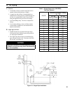
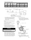
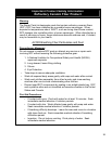
Boiler
Model
Firing Rate
(GPH)
Burner
Model
Delavan Oil
Nozzle
Settings
Air Gate
Pump Pressure
(PSIG)
Turbulator
LEDV1 0.60 BF3 0.50 - 60° A 4.0 145 0
LEDV2 1.00 BF5 0.85 - 60° A 5.0 145 1.0
LEDV3 1.25 BF5 1.00 - 60° A 6.5 145 3.0
Table 6A: Riello BF Burner Settings
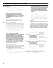
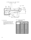
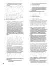
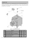
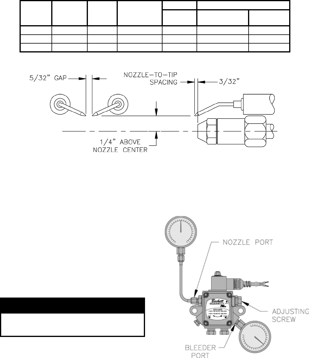
Figure 20A: Electrode Tip Gap & Spacing
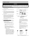
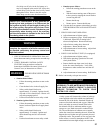
8. INSTALL PRESSURE GAUGE
a. Either, remove plastic hose and oil pump vent
tting, then, install a reliable pressure gauge
into vent tting port, or install the gauge into the
nozzle port. See Figure 20B.
Figure 20B: Checking / Adjusting Fuel
Pump Pressure
9. CHECK / ADJUST OIL PRESSURE
a. Check oil pressure to correspond to a specied
value for a particular LEDV boiler model. Refer
to Table 6.