


24
After approximately 60 seconds without
any key pressed, the display will enter a
dim display mode. To return to the bright
display mode, simply press any key.
2. Control Operating Characteristics
The L7248/L7224 can be in any three (3)
operational states: Normal, High-Limit and Error.
The controller moves back and forth from High-
Limit to Normal state as part of normal operation.
The controller will enter the Error state when there
is an abnormal condition. The operating states are:
a. Normal: Boiler temperature has gone below the
high limit setting (minus the differential) and has
not exceeded the high limit setting.
b. High-Limit: Boiler temperature has gone above
the high limit setting and has not dropped below
the high limit setting (minus the differential).
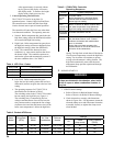
c. Error: The controller has detected an error
condition (e.g., open sensor) and has shut down
the burner output. The controller continues to
monitor the system and automatically restarts if
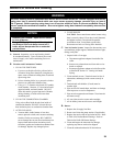
the error condition clears. See Table 4.
Table 4: LED Error Codes
Error Code Cause/Action
Err1 Sensor fault; check sensor.
Err2 ECOM fault; check EnviraCom™ wiring.
Err3 Hardware fault’ replace control.
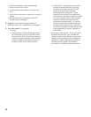
d. Low-Limit: Boiler temperature has gone
below the low limit setting (minus the low limit
differential) and has not gone above the low limit
setting.
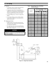
e. The operating sequence for L7248/L7224 is
described below and shown in Table 5.
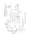
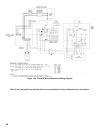
The switching action in the L7248/L7224 control
has one setting, the high limit, see Figure 14.
The switching relay is controlled by the low
voltage room thermostat. On a call for heat, the
relay contacts make to complete the line voltage
circulator circuit and also the burner circuit if the
boiler water temperature is below the high limit
Table 5: L7248/L7224 Controller
Operating Sequence
noitcA esnopseRmetsyS
tatsomrehT
rofsllac
taeh
.stratsrotalucriC
renruB.dekcehcsierutarepmetrelioB
sierutarepmetretawehtnehwstratser
.gnittestimilhgihwoleb
relioB
ehtsdeecxe
timilhgih
nehwstratserrenruB.ffodenrutsirenruB
ehtwolebsporderutarepmetretaweht
.laitnereffidehtsunimgnittestimilhgih
tatsomrehT
deifsitassi
.ffonrutrenrubdnarotalucriC
rorrE
noitidnoc
stuptuolla,detcetedsinoitidnocrorrenafI
lortnoC.ffosirenruB.nwodtuhsera
nehwstratserdnanoitcnufotseunitnoc
.detcerrocsirorre
eht,ecneuqeskcehcrorreehtgniruD
dnarosnesehtnitfirdrofskcehcmetsys
.snoitcennocehtninoisorroc
setting. The high limit switch shuts off the burner
if boiler water temperature exceeds the high limit
setting. The circulator will continue to operate
as long as the thermostat is calling for heat. The
high limit automatically resets after the water
temperature drops past the setpoint and through
the differential.
F. BURNER START-UP
WARNING
Do not attempt to start the burner when excess
oil has accumulated in the chamber, when boiler
is full of vapor or when combustion chamber is
very hot.
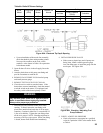
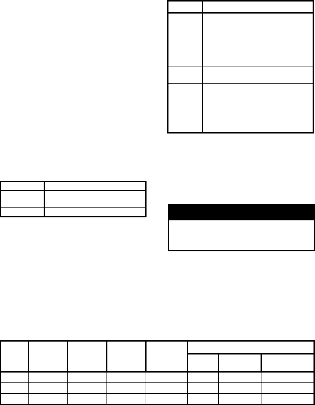
1. VERIFY burner settings.
a. Refer to Table 6 for Beckett Burner Settings.
Refer to Table 6A for Riello BF Burner Settings.
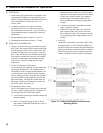
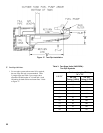
b. Check electrodes to comply with dimensions
shown in Figure 20A. For adjustment, loosen the
electrode clamp screw and slide/rotate electrodes
as needed. Securely re-tighten the clamp screw
when nished.
Boiler
Model
Firing Rate
(GPH)
Burner
Model
Air Tube
Combination
Delavan
Nozzle
Settings
Air
Head
(stop screw)
Pump Pressure
(PSIG)
LEDV1 0.60 AFII 85 HLX50HD 0.50 x 70°B 2.5 #2 140
LEDV2 1.00 AFII 150 HLX50HE 0.85 x 60°B 3.5 #3 140
LEDV3 1.25 AFII 150 HLX50HE 1.00 x 60°B 4.0 #5 140
Table 6: Beckett AFII Burner