


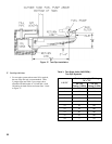
18
V. Electrical and Sequence of Operations
A. ELECTRICAL
1. Install wiring and ground boiler in accordance with
requirements of authority having jurisdiction, or in
absence of such requirements the National Electrical
Code, ANSI/NFPA 70, and/or the CSA C22.1
Electric Code.
2. A separate electrical circuit must be run from
the main electrical service with an over-current
device/disconnect in the circuit. A service switch is
recommended and may be required by some local
jurisdictions.
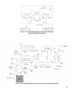
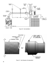
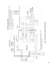
3. Wiring should conform to Figures 15 and 15A.
4. Thermostat heat anticipator setting = 0.3 amp.
B. SEQUENCE OF OPERATIONS
1. General
. A call for heat by the thermostat energizes
the L7248C limit control which in turn energizes the
R7184P primary control to turn on the burner. The
circulator will operate as long as there is a call for
heat. If the call for heat is not satised and the high
limit setting is reached, the circulator will continue
to operate, and the burner will stop until the high
limit circuit is closed by a drop in boiler water
temperature.
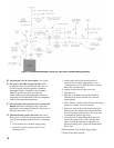
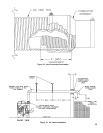
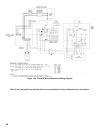
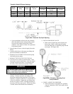
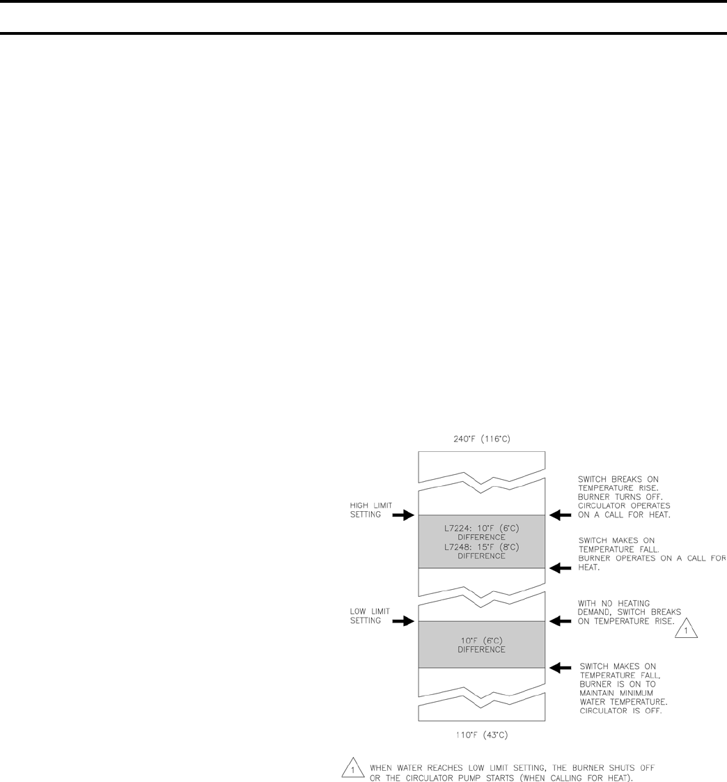
2. L7248C Combination Limit control.
The switching action within the L7248C control has
one setting, the high limit. The switching relay is
controlled by the low voltage room thermostat. On
a call for heat, the relay contacts close to complete
the line voltage circulator circuit and also the burner
circuit if the boiler water temperature is below the
high limit setting. The high limit switch shuts off
the burner if boiler water temperature exceeds the
high limit setting. See Figure 14.
3. R7184P Oil Primary Control.
The R7184P operates the oil burner motor, solenoid
oil valve, and the electronic ignitor in response to a
call for heat from the L7248C limit control.
a. A call for heat will energize the burner motor and
electronic ignitor.
b. After a 15 second pre-purge period, in which
time a draft is established in the ueways, the oil
valve is opened.
c. If the burner ignites within 15 seconds from the
time the oil valve opens and the CAD cell senses
a ame, the electronic ignitor is de-energized
and the burner will operate until the call for
heat is satised or the setting of the high limit is
reached.
d. A manual reset button is provided to reset the
safety switch after lockout.
e. When the call for heat ends, or the CAD cell
fails to sense a ame, the oil valve will close.
The combustion blower will continue to operate
for a postpurge period of approximately two (2)
minutes.
4. CAD Cell.
The Beckett AFII burners used on the LEDV Series
are supplied with a C554A Cadmium Sulde (cad
cell) Flame Detector to monitor the burner ame and
shut down the burner on ignition failure or on ame
failure during the run cycle. On either failure, the
manual reset button on the R7184P will be tripped.
Figure 14: L7248/L7224 Setpoint and Differential
Switching Action