


INSTALLATION OF
OPTIONAL
BLOWER ASSEMBLY
(MODEL MA CVF714)
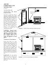
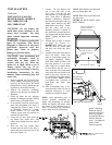
WARNING: Failure to position the parts in
accordance with this diagram or failure to use
only parts specifically approved may result in
improper functions, or property damage, or per-
sonal injury.
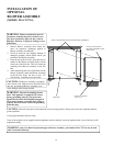
1. Remove Blower Assembly from carton. Re-
move all protective packaging applied to
Blower Assembly for shipment.
2. Check all items for any shipping damage. If
damaged, promptly inform dealer where you
purchased the Blower Assembly.
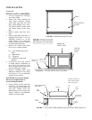
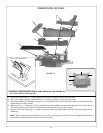
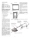
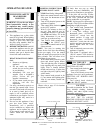
3. From the rear of the Fire Box, align the four (4)
notches in the Blower Assembly with (4) holes
in the rear of the Fire Box. This will ensure the
centering of the Blower Assembly on the Fire
Box.
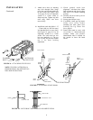
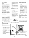
4. After determining the area of placement for the
Blower Assembly, attach the Blower Assembly
to the Fire Box using the four (4) #8 x 1/2"
self-piercing mounting screws provided.
CAUTION: The Blower Assembly is equipped
with a Power Cord. Make sure that the Power Cord
does not get under the Blower Assembly or be-
come damaged while being installed.
WARNING: Electrical Grounding Instruc-
tions: This appliance is equipped with a three
prong (grounding) plug for your protection
against shock hazard and should be plugged di-
rectly into a properly grounded three-prong re-
ceptacle. DO NOT cut or remove the grounding
from this plug.
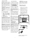
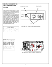
BLOWER ASSEMBLY
(MA CVF714)
FIRE BOX
CAUTION: Label all wires prior to disconnection when servicing controls. Wiring errors can cause improper and dan-
gerous operation.
Verify proper operation after servicing.
If any of the original wire as supplied with the appliance must be replaced, it must be replaced with a wire of at least a 105€
temperature rating.
FOUR (4) HOLES FOR MOUNTING BLOWER ASSEMBLY
FOUR (4) NOTCHES IN
BLOWER ASSEMBLY FOR
MOUNTING
WARNING: Only New Buck Corporation approved blower assembly, part number MA CVF714, may be used
with Townsend II unit only.
13