


INSTALLATION
Continued
STOVE CAVITY ASSEMBLY
1. Lift off corrugated box enclosing
stove body crating.
2. Remove all screws fastening the
wood frame enclosure. Spread
wood frame open and lift away
from plastic-bagged stove body.
The bottom pieces of pallet wood
will remain bolted to the stove
body.
3. Remove plastic bag from stove
body.
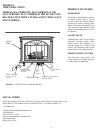
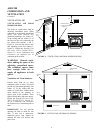
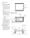
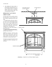
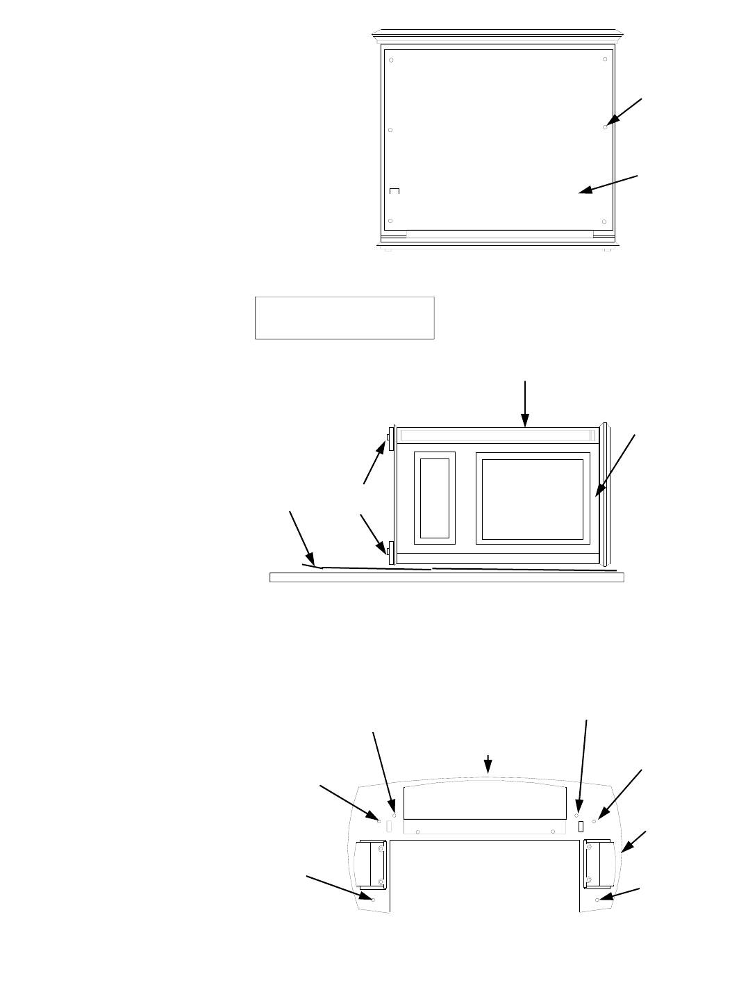
4. Remove back panel from stove, if
equipped (See Figure 5). Use an
adjustable wrench or a 10 mm
socket. Remove six (6) bolts and
washers. Keep bolts and washers
to reattach back panel later.
5. Remove all contents from inside
stove cavity. Contents include:
(4) - Legs (includes leg leveler
bolts)
(1) - Bottom door
(3) - Top grates
(1) - Hardware kit bag with
fasteners
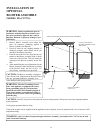
6. Carefully lay stove body on back
to attach bottom components to
stove body (See Figure 6). Rest
stove on drop cloth or blanket to
avoid scratching stove edges.
7. Remove remaining pallet wood
attached to bottom of stove body
(See Figure 6). Use an adjustable
wrench to remove bolts.
CAUTION: Cast Iron is brittle.
Do not over-tighten bolts or
screws during assembly.
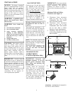
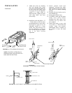
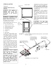
8.
Fasten each leg to stove with four
(4) M8 x 1.25—20 mm bolts. Use
a flat washer and lock washer with
each bolt. Tighten bolts into
threaded holes on stove body (See
Figures 7 and 8). Use an adjustable
wrench or a 12mm socket.
BOLT
BACK STOVE
PANEL
FIGURE 5 - REMOVING BACK PANEL
FIGURE 6 - LAYING DOWN STOVE ON SIDE
TOP OF
STOVE
UNIT
FRONT OF
STOVE UNIT
DROP CLOTH/
BLANKET
REMOVE PALLET
BOLTED TO
STOVE BOTTOM
BOTTOM OF
STOVE UNIT
LEG
HOLE
LEG
HOLE
DOOR CATCH BOLT
WITH ADJUSTABLE
HEX NUTS HOLE
FRONT
DOOR HINGE STEP
BOLT HOLE
LEG
HOLE
LEG
HOLE
FIGURE 7 - LOCATING THREADED HOLES FOR STOVE BOTTOM,LEGS
NOTE: CVF200’s series are
not equipped with a back panel.
7