


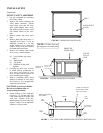
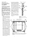

INSTALLATION
INSTALLING GAS LOG
HEATER FIREBOX MODELS
MA CVFB200LP OR
MA CVFB200NAT
CAUTION: Do not remove the metal
data plates attached to the heater as-
sembly. The data plates contain impor-
tant warranty information.
WARNING: Failure to position the
parts in accordance with theses dia-
grams or failure to use only parts spe-
cifically approved with this heater may
result in property damage or personal
injury.
CAUTION: After installation and
periodically thereafter, check to ensure
that no flame comes in contact with any
log. If so, reposition logs according to
the log installation instructions in this
manual. Flames contacting logs will
create soot.
1. Remove logs and heater from carton.
NOTE: Do not pick up gas heater by
the burner itself. This could damage
heater. Always handle the heater by
the firebox only.
2. Remove all protective packaging ap-
plied to logs and gas log heater for
shipment.
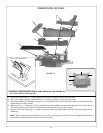
3. Check all items for any shipping
damage. If damaged, promptly inform
dealer where you bought heater. Place
the logs into the Firebox and follow
the directions on page 10, Figure 13.
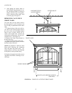
4. If not already removed, remove back
panel from assembled stove body
(Stoves sold for the use of a Model
CVF200’s series may not have a back
panel, just the bolts). See back panel
and bolts on page 7, Figure 5. Use a
10mm socket or an adjustable
wrench. Remove six (6) bolts and
washers. Keep bolts and washers to
attach Rear Mounting Brackets.
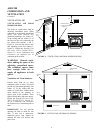
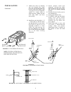
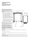
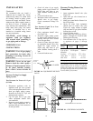
5. From rear of stove slide the Firebox
into the Cast Stove until the front of
the Firebox touches the inner front
rear side of the stove. The Firebox
has two Alignment Guides made to
the bottom of the Firebox. These will
ensure a more proper center align-
ment of the Firebox in the Cast Stove.
Then take the mounting bracket with-
out a switch holder and align slots in
bracket with top and bottom holes on
right side of stove. Fasten with bolts
provided. (See Figure 14)
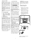
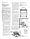
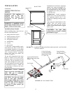
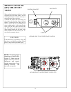
6. Inside of Firebox you will find three
(3) wires with a switch attached. Dis-
connect the wires from the switch.
Using the remaining mounting bracket
with the switch holder on top, feed
the wires through the wire channel
starting at the end opposite the switch
holder. Continue through the switch
hole in top. Reconnect the three (3)
wires to the switch (make sure the red
wire is connected to the Manual side
of the switch, see page 33). Position
the switch in the switch holder, press
until switch locks into position. (See
Figure 15). Take mounting bracket
and attach to left rear side of stove,
with bolts provided. (See Figure 14)
7. Place freestanding stove in desired
position in room. Be sure to maintain
clearances to combustibles as outlined
on page 6.
8. After positioning stove in desired po-
sition, connect gas supply and com-
plete all pressure checks and light the
heater. (See page 14 Connecting To
Gas Supply)
BOLTS
RIGHT
REAR
SIDE
LEFT
REAR
SIDE
Alignment Guides
BOLTS
FIGURE 14 - BACK OF STOVE WITH FIREBOX INSERT / MOUNT-
ING BRACKETS / SWITCH/ OPTIONAL AIR CHANNEL WITH
BLOWER.
SWITCH
OPTIONAL AIR CHANNEL/
BLOWER ASSEMBLY
OFF AUTO
WIRE
CHANNEL
SWITCH
HOLDER
SWITCH
MOUNT-
ING
BRACKET
FIGURE 15 - BRACKET/WIRE
CHANNEL
SWITCH HOLDER (ALSO REFER TO
PAGE 16)
MOUNTING BRACKETS
MANUAL
RED
WIRE
11