


INSTALLATION
VENT ASSEMBLY
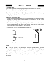
There are two basic types of installations approved with your model DV23ZC appliance.
These are: Horizontal termination (See Figure 5)
Vertical termination (See Figure 10)
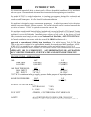
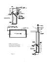
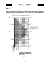
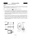
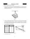
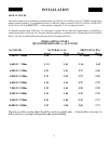
When planning your installation, refer to Figure 3 to ensure the length of your vent falls into the
limits specified in Figure 3. Also consult page 9, “Exterior Vent Locations and Restrictions”
regarding the placement of the vent terminal.
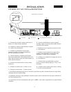
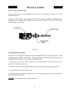
HORIZONTAL TERMINATION
1. Set the gas appliance in its desired location. Check to determine if wall studs or roof rafters
are in the way when the venting system is attached. If this is the case, you may want to
adjust the location of the appliance.
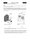
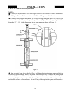
2. Dura-Vent pipe and fittings are designed with special twist-lock connections. Assemble the
desired combination of pipe and elbows to the appliance adapter with pipe seams oriented
towards the wall or floor, as much out of view as possible.
3. Use only Dura-Vent #985 horizontal termination (wind cap).
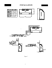
Figure 4 Figure 5
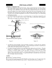
NOTE:
Twist-lock procedure: Four indentations, located on the female ends of pipes and
fittings, are designed to slide straight onto the male ends of adjacent pipes and fittings, by
orienting the four pipe indentations so they match and sliding into the four entry slots on the
male ends (Figure 4). Push the pipe sections completely together, then twist-lock one section
clockwise approximately one-quarter turn, until the two sections are fully locked.
Horizontal runs of vent must be supported every three feet. Wall straps are available for
this purpose.
MALE LOCKING
SOCKET
FEMALE LOCK-
ING SOCKET
11