


Pressure Testing Gas Supply Piping System
Note: The appliance and its appliance main valve must be disconnected from the gas supply piping
system during any pressure testing of that system at test pressures in excess of 1/2 psi. (3.5 kPa).
The appliance must be isolated from the gas supply piping system by closing its equipment shutoff
valve during any pressure testing of the gas supply piping system at test pressures equal to or less
than 1/2 psi. (3.5 kPa).
Test Pressures In Excess of 1/2 PSIG (3.5 kPa)
1. Disconnect appliance with its appliance main gas valve (control valve) and equipment shutoff
valve from gas supply piping systems. Pressures in excess of 1/2 psig (3.5 kPa) will damage
burner system gas regulator.
2. Cap off open end of gas pipe where equipment shutoff valve was connected.
3. Pressurize supply piping system by either opening propane/LP supply tank valve for propane/LP
gas burner system or opening main gas valve located on or near gas meter for natural gas burner
system, or using compressed air.
4. Check all joints of gas supply piping system. Apply commercial leak test solution to all gas
joints. Bubbles forming show a leak. Correct all leaks at once.
5. Reconnect burner system and equipment shutoff valve to gas supply. Check reconnected fittings
for leaks.
Test Pressures Equal To or Less Than 1/2 PSIG (3.5 kPa)
1. Close equipment shutoff valve.
2. Pressurize supply piping system by either opening propane/LP supply tank valve for propane/LP
gas burner system or opening main gas valve located on or near gas meter for natural gas burner
system, or using compressed air.
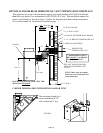
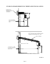
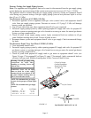
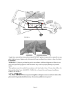
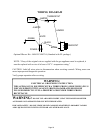
3. Check all joints from propane/LP supply tank or gas meter to equipment shutoff valve (see
Figure 34, page 17 for propane/LP or Figure 35, page 17 for natural). Apply commercial leak test
solution to all gas joints. Bubbles forming show a leak. Correct all leaks at once.
OPEN
CLOSED
EQUIPMENT
SHUTOFF
VALVE
EQUIPMENT SHUTOFF VALVE
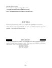
Warning: Test all gas piping and
connections for leaks after
installing or servicing. Correct all
leaks at once.
WARNING: Never use an open
flame to check for a leak. Apply
commercial leak test solution to all
gas joints. Bubbles forming show a
leak. Correct all leaks at once.
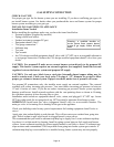
NOTE: The minimum inlet gas supply
pressure for the purpose of input adjust-
ment.
NOTE: The maximum inlet gas supply
pressure.
LP NATURAL
PRESSURE: 10.0" W.C. 3.5" W.C.
*MIN. INLET 11.0" W.C. 4" W.C.
MAX. INLET 13.0" W.C. 10.5" W.C.
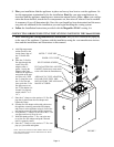
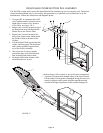
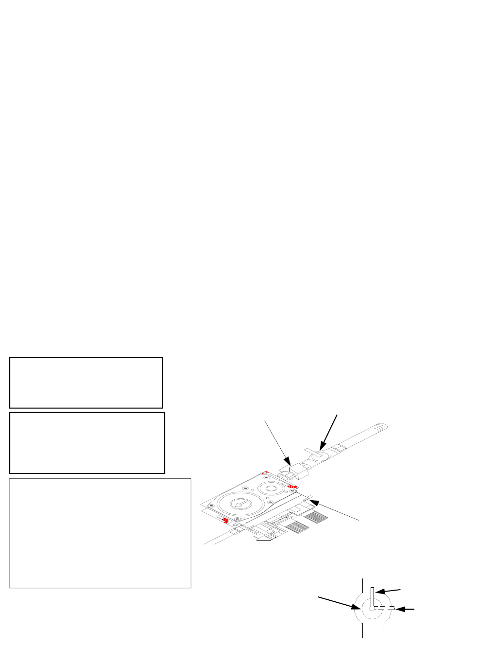
Gas Control
CSA/AGA Design-
Certified Equipment
Shutoff Valve With
1/8" NPT Tap
Union
FIGURE 13
Page 17