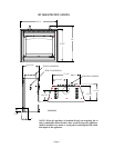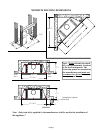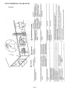
DV1000
DIRECT VENT TERMINATION
INSTALLATION INSTRUCTIONS
(MAGNAFLEX)
Read the instructions in this manual completely before installing the DV1000 appliance with
the Magnaflex vent system. Magnaflex Venting systems are packaged with installation instruc-
tions, the instructions must be followed exactly for your safety and to prevent voiding the war-
ranty of your appliance and venting system.
The DV1000 will operate safely when installed in accordance with this instruction manual.
Read all instructions before starting installation, then follow these instructions carefully to
maximize fireplace performance and safety. Report damaged parts to your dealer.
Any common venting of the gas appliance using DV vent kit with other gas appliances is not
allowed. Do not connect this appliance to a chimney flue serving a separate solid fuel-burning
appliance.
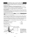
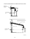
WAR NIN G: Always maintain minimum clearances around vent systems. The minimum
clearance to combustibles for horizontal vent pipe is 3 inches at the top and 1 inch at the
bottom of the vent system until the flue penetrates the nearest vertical wall.
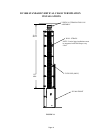
FOR WALL FIRESTOPS AND VERTICAL RUNS ONLY, maintain a 1 inch minimum
clearance from all sides of the vent. Do not pack the open air spaces around the fireplace
or flue with insulation or other materials. Any horizontal run must have a 1/4” rise for
every one (1) foot of run towards the vent termination. Never install the vent level or
downward.
WAR NIN G: Contact your Local Building and Fire Officials about restrictions and in-
stallation inspections in your area.
IMPORTANT SAFETY INFORMATION
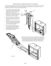
∗ The termination cap MUST be vented directly to the outside. The termination kit MUST
NEVER be connected to a chimney flue(s) servicing a separate solid-fuel burning appliance
or any other appliance.
∗ Termination cap MUST NOT be recessed into a wall or siding.
∗ The flexible vent pipe cannot be intermingled with any of the rigid vent pipe section. DO
NOT connect two sections of flexible vent pipe together to achieve a longer length without
approved connectors.
∗ Horizontal runs must be supported every 3 feet using wall straps. Vertical runs must be sup-
ported every 8 feet using wall straps. Slip wall straps loosely on to pipe. Attach straps to
framing members using nails or screws. Tighten nut/bolt to secure pipe.
∗ The fireplace and venting system should be inspected before initial use and at least annually
by a qualified field service person. Inspect external vent cap on a regular basis to make sure
that no debris is interfering with the airflow. Inspect entire venting system to ensure proper
function.
∗ Vent connections should overlap a minimum of 1” for proper sealing.
∗ Always stretch and secure venting with metal strapping secured with nails (nails and strap-
ping not supplied) to ensure that the horizontal runs remain true.
Page 9


