


—
9
—
START-UP
I. START-UP AND ADJUSTMENTS
A. Checking Cooling Control Operation
Start and check the unit for proper cooling control operation
as follows:
1. Place room thermostat SYSTEM switch in OFF posi-
tion. Observe that blower motor starts when FAN
switch is placed in ON position and shuts down when
FAN switch is placed in AUTO. position.
2. Place SYSTEM switch in COOL position and FAN
switch in AUTO. position. Set cooling control below
room temperature. Observe that compressor and con-
denser- and evaporator-fan motors start. Observe
that cooling cycle shuts down when control setting is
satisfied.
B. Unit Controls
All units have the following internal-protection controls:
Compressor Overload
This overload interrupts power to the compressor when
either the current or internal motor winding temperature
become excessive, and automatically resets when the inter-
nal temperature drops to a safe level. This overload may
require up to 60 minutes (or longer) to reset. If the internal
overload is suspected of being open, disconnect the electrical
power to the unit and check the circuit through the overload
with an ohmmeter or continuity tester.
Time Guard® II Device
The unit is equipped with accessory Time Guard II recycle
timer. The device will cause a 5-minute delay between com-
pressor starts.
Cycle-LOC™ Device
When high-pressure or low-pressure fault occurs, the Cycle-
LOC device will protect the system by not allowing the com-
pressor to start.
Low-Pressure Switch/(LPS)
When the suction line pressure drops below 7 psig (48 kPa),
the LPS opens 24-v power to the compressor contactor and
stops the compressor. When the pressure reaches 22 psig
(152 kPa), the switch resets and the compressor is allowed to
restart.
High-Pressure Switch
(HPS)
When the refrigerant high-side pressure reaches 426 psig
(2937 kPa), the HPS opens 24-v power to the compressor con-
tactor and stops the compressor. When the pressure drops to
320 psig (2206 kPa), the switch resets and the compressor is
allowed to restart.
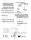
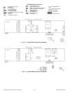
C. Sequence of Operation
At start-up, the thermostat calls for cooling. When all
safety devices are satisfied, the compressor contactor (fan
contactor) will energize causing the compressor and outdoor
(condenser) fan motor to operate. Terminal
“
G
”
at the
thermostat is also energized, allowing the field-supplied
and -installed (24v) indoor (evaporator) fan contactor to func-
tion. A field-supplied and -installed liquid line valve (con-
nected between Terminals G and C at the outdoor unit), will
also open. This allows the system to function in cooling; the
LPS will not open if compressor is not running. As cooling
demand is satisfied, the thermostat contacts break, deener-
gizing the contactor causing the system to shut off. The liq-
uid line solenoid (LLS) valve closes, minimizing the potential
for refrigerant migration at this time. The compressor does
not restart until the thermostat again calls for cooling. If a
demand for cooling occurs within 5 minutes after the ther-
mostat is satisfied, the system will not restart due to the fea-
ture of Time Guard II device. After the 5-minute time period,
the system will restart as normal upon thermostat demand.
The system is protected with a Cycle-LOC device so that the
compressor will not start if a high-pressure or low-pressure
fault occurs. To reset the Cycle-LOC device, set the thermo-
stat to eliminate the cooling demand then return to the orig-
inal set point. This should be done only once, and if system
shuts down due to the same fault, determine the problem
before attempting to reset the Cycle-LOC device.
The crankcase heaters must be energized for a minimum of
24 hours before starting a 569C and 576B unit.
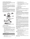
D. Oil Charge
576B Units
Allow unit to run for about 20 minutes. Stop unit and check
compressor oil level. Add oil only if necessary to bring oil into
view in sight glass. Use only approved compressor oil.
Approved oils are:
Suniso 3GS
WF32-150
If oil is added, run unit for an additional 10 minutes. Stop
unit and check oil level. If level is still low, add oil only after
determining that piping system is designed for proper oil
return and that system is not leaking oil.
569C Units
The 569C units do not have a sight glass and are factory
charged with the correct amount of oil.
All Units
Do not reuse drained oil or use any oil that has been exposed
to the atmosphere. Procedures for adding or removing oil are
given in the Standard Service Techniques Manual, Chapter
1, Refrigerants.
CARE AND MAINTENANCE
To ensure continuing high performance and to minimize the
possibility of premature equipment failure, periodic mainte-
nance must be performed on this equipment. This cooling
unit should be inspected at least once each year by a quali-
fied service person.
NOTE TO EQUIPMENT OWNER: Consult your local dealer
about the availability of a maintenance contract.
CAUTION: Complete the required procedures
given in the Pre-Start-Up section and unit start-up
checklist at the end of this publication before starting
the unit. Do not jumper any safety devices when oper-
ating the unit.
Do not operate the compressor when the outdoor tem-
perature is below 25 F (
2
4 C) (unless accessory low
ambient kit is installed).
WARNING: The ability to properly perform main-
tenance on this equipment requires certain expertise,
mechanical skills, tools, and equipment. If you do not
possess these, do not attempt to perform any mainte-
nance on this equipment other than those procedures
recommended in the User’s Manual. FAILURE TO
HEED THIS WARNING COULD RESULT IN SERI-
OUS PERSONAL INJURY AND POSSIBLE DAM-
AGE TO THIS EQUIPMENT.