


—
8
—
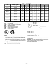
VI. ACCESSORY INSTALLATION
At this time any required accessories should be installed on
the unit. Refer to Table 5 for available accessories. Control
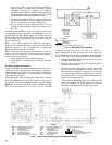
wiring information is provided in the unit wiring book.
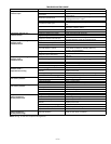
Table 5 — Accessory List
PRE-START-UP
Proceed as follows to inspect and prepare the unit for initial
start-up:
1. Field electrical power source must agree with unit
nameplate rating.
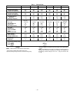
2. Check voltage imbalance as shown in Table 4, Note 2.
3. Check that all internal wiring connections are tight
and that all barriers, covers, and panels are in place.
4. Ensure all service valves are open. On 576B units, be
sure all compressor service valves are backseated.
5. Verify that compressor holddown bolts have been
loosened and that flat/snubber washers can be
rotated by applying finger pressure (snug, but not
tight).
6. On 569C and 576B units, verify compressor crank-
case heater is securely in place. Crankcase heater
must operate for a least 24 hours before start-up.
7. Note that compressor oil level is visible in the sight
glass (576B units only).
8. Check for leaks in refrigerant system by using soap
bubbles and/or electronic leak detector.
9. Check that liquid line solenoid valve is located at
evaporator coil as shown in Filter Drier and Moisture
Indicator section, page 5.
10. Check that both outdoor and indoor units are prop-
erly mounted in accordance with installation instruc-
tions and applicable codes.
ACCESSORY
Gage Panel
Winter-Start Relay Package
Weatherprobe™ II Low Ambient Kit
Hail Guard Package (072)
Hail Guard Package (090,102,120)
Thermostats
Subbase
WARNING: Failure to observe the following warn-
ings could result in serious personal injury:
1. Follow recognized safety practices and wear
protective goggles when checking or servicing
refrigerant system.
2. Do not operate compressor or provide any elec-
tric power to unit unless compressor terminal
cover is in place and secured.
3. Do not remove compressor terminal cover until
all electrical sources have been disconnected.
4. If refrigerant leak is suspected around compres-
sor terminals, recover refrigerant whenever
possible and relieve all pressure from system
before touching or disturbing anything inside
terminal box.
5. Never attempt to repair soldered connection
while refrigerant system is under pressure.
6. Do not use torch to remove any component.
System contains oil and refrigerant under
pressure. To remove a component, wear protec-
tive goggles and proceed as follows:
a. Shut off electrical power to unit.
b. Recover refrigerant. Relieve all pressure
from system.
c. Cut component-connecting tubing with tub-
ing cutter and remove component from unit.
d. Carefully unsweat remaining tubing stubs
when necessary. Oil can ignite when exposed
to torch flame.
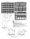
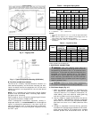
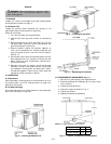
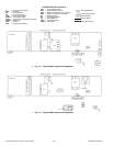
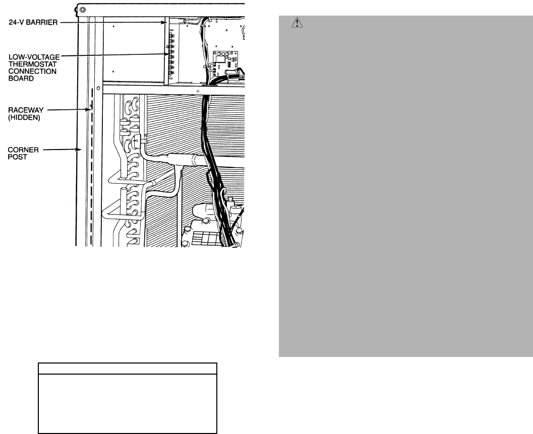
Fig. 7 — Field Control Wiring Raceway
(576B Unit Shown)