


—
6
—
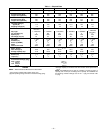
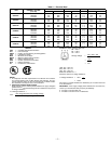
the current within 10%. Use the formula shown in
Table 4, Note 2, to determine the percent voltage
imbalance. Operation on improper line voltage or
excessive phase imbalance constitutes abuse and may
cause damage to electrical components. Such opera-
tion would invalidate any applicable warranty.
4. Insulate low-voltage wires for highest voltage con-
tained within conduit when low-voltage control wires
are run in same conduit as high-voltage wires.
5. Do not damage internal components when drilling
through any panel to mount electrical hardware, con-
duit, etc.
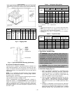
All units except 208/230-v units are factory wired for the
voltage shown on the nameplate. If the 208/230-v unit is to
be connected to a 208-v power supply, the transformer must
be rewired by moving the black wire from the 230-v terminal
on the transformer and connecting it to the 200-v terminal
on the transformer.
Refer to unit label diagram for additional information.
Pigtails are provided for field wire connections. Use factory-
supplied splices or UL (Underwriters’ Laboratories)
approved copper/aluminum connector.
When installing units, provide a disconnect per NEC. All
field wiring must comply with NEC and local requirements.
Install field wiring as follows:
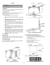
1. Install conduit through side panel openings.
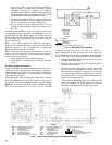
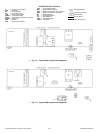
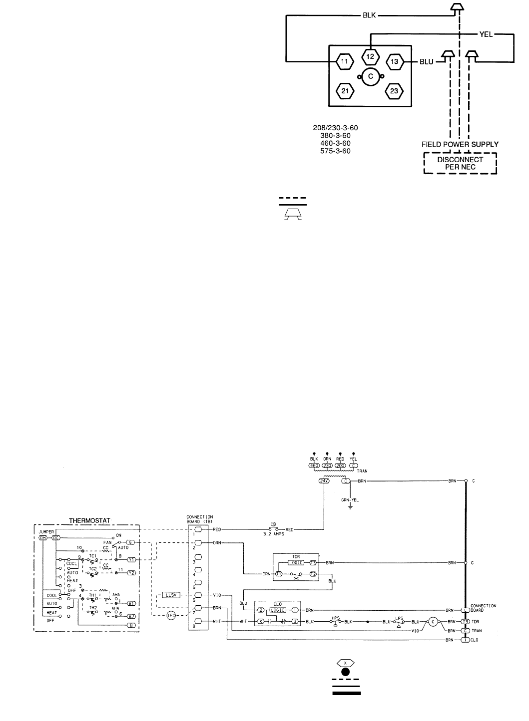
2. Install power lines to terminal connections as shown
in Fig. 5.
B. Control Voltage Connections
Install an accessory thermostat assembly according to instal-
lation instructions included with the accessory. Locate ther-
mostat assembly on a solid wall in the conditioned space to
sense average temperature in accordance with thermostat
installation instructions.
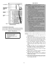
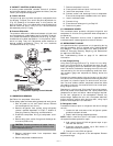
Route thermostat cable or equivalent single leads of colored
wire from subbase terminals to low-voltage connections on
unit (shown in Fig. 6) as described in Steps 1 through 4 below.
NOTE: For wire runs up to 50 ft, use no. 18 AWG insulated
wire (35 C minimum). For 50 to 75 ft, use no. 16 AWG
insulated wire (35 C minimum). For over 75 ft, use no. 14
AWG insulated wire (35 C minimum). All wire larger than
no. 18 AWG cannot be directly connected to the thermostat
and will require a junction box and splice at the thermostat.
1. Connect thermostat wires to screw terminals of low
voltage connection board.
2. Pass the control wires through the hole provided in
the corner post. See Fig. 7.
3. Feed wire through raceway built into the corner post
and into the 24-v thermostat connection board. The
24-v thermostat connection is located on the left side
of the low voltage connection compartment. The race-
way provides the UL required clearance between the
high- and low-voltage wiring.
4. Total combined amperage draw of the field-installed
liquid line solenoid valve and indoor fan contactor
must not exceed 22 va. If the specified va must be
exceeded, use a remote relay to switch the load.
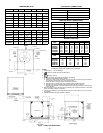
LEGEND
Fig. 5 — Power Wiring Connections
C—
Contactor
NEC —
National Electrical Code
Field Wiring
Factory Wiring
Splice Connection (Factory Supplied)
LEGEND
AHA —
Adjustable Heat Anticipator
LLSV —
Liquid Line Solenoid Valve
C—
Contactor, Compressor
LPS —
Low-Pressure Switch
CB —
Circuit Breaker
TB —
Terminal Block
CC —
Cooling Compensator
TC —
Thermostat-Cooling
CLO —
Compressor Lockout
TDR —
Time-Delay Relay
HPS —
High-Pressure Switch
TH —
Thermostat-Heating
IFC —
Indoor (Evaporator) Fan Contactor
TRAN —
Transformer
Terminal (Marked)
Spice
Factory Wiring
Field Control Wiring
To Indicate Common Potential Only,
Not To Represent Wiring
Fig. 6 — Typical Control Wiring Connections (569C Shown)
→
801